DISASSEMBLY
PART 5
Page 87
Note: Make a note of the orientation of the brush wire exit
passage on the stator. During re-assembly, if the stator is
not bolted together with the exit passage in the same loca-
tion, the brush wires will not be long enough to reconnect
to the wire harness.
20. Remove brush assembly using a 7mm socket.
Figure 88.
21. Slide the stator assembly off the rotor.
Figure 89.
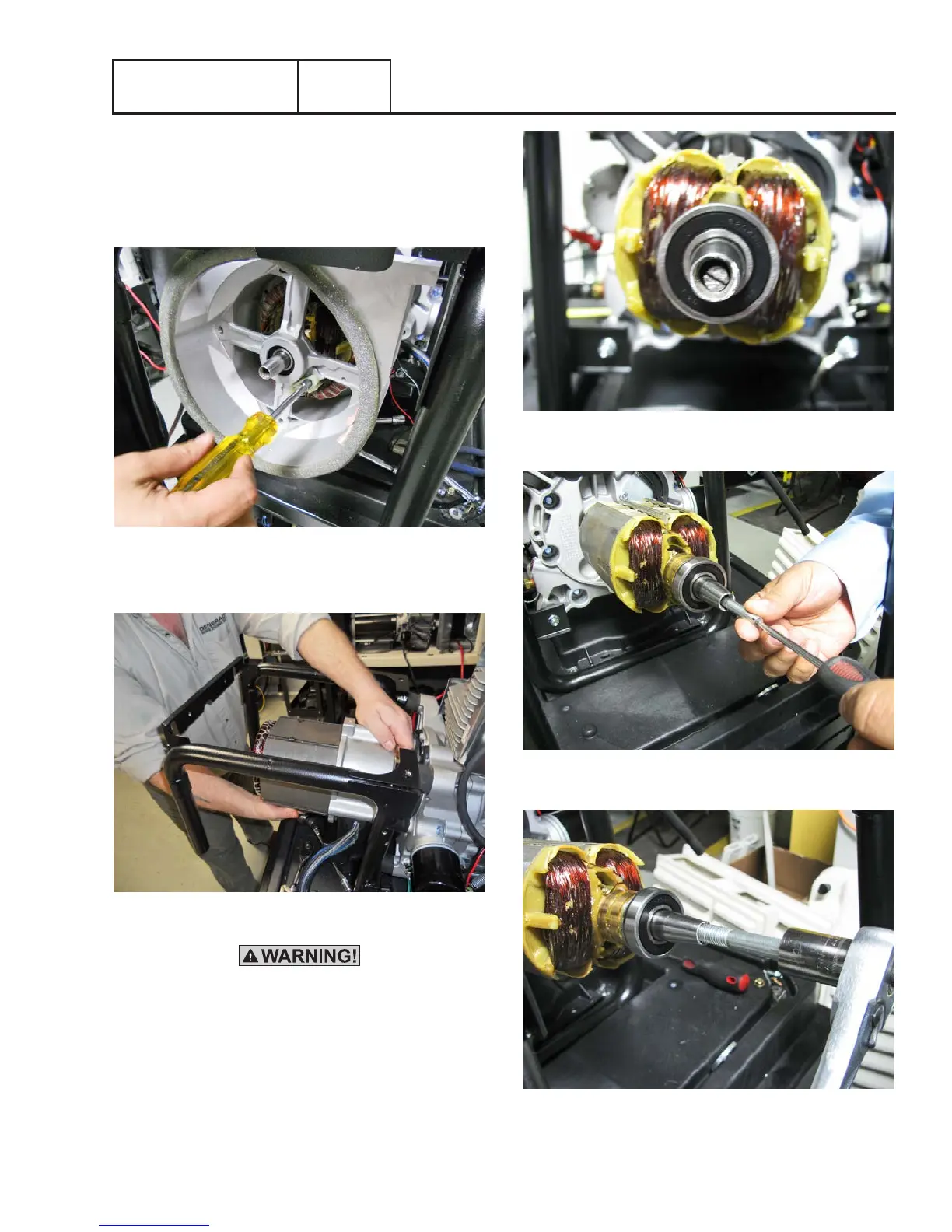
Warning! Do not cut the rotor bolt unless you have a
replacement rotor bolt.
22. Rotor Removal: Cut 2.5 inches from the rotor bolt.
Slot the end of the bolt to suit a flat blade screwdriver.
Slide the rotor bolt back through the rotor and use a
screwdriver to screw it into the crankshaft. Use a 55mm
M6 x1.00 bolt to screw into rotor. Apply torque to the
55mm M6 x1.00 bolt until taper breaks.
Figure 90.
Figure 91.
Figure 92.
Section 5.1
Major Disassembly