GM Energy V2H Bundle Installation Manual 76
Appendix H: System & Voltage Checks Form, with technician names legibly recorded and date and time entered. Take a
photo of the form for your job closeout records, and then fold it up and place it inside the Hub front cover before closing and
sealing the Hub door. Additionally, GM Energy recommends taking the following photos for your closeout record. Be aware,
certain photos can only be taken mid-install, as noted below; others should be taken before covers are fastened to reduce time
spent.
Photos for Charger-Only Installations
Photo Taken
During Install
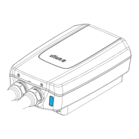
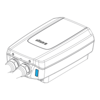
Charger (middle cover, attached screws visible)
High chance of water ingress; verify middle
cover is attached properly.
Charger (cover removed, all wiring terminations
visible, showing conduit/wire entry points)
Verify wiring workmanship and terminations.
Charger (cover removed, showing DIP switch
settings)
Refer to Section 4.2.
Verify DIP switch setting.
You must verify that the DIP switch setting does
not exceed capability of circuit per code
requirements
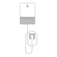
Charger (two feet away from Charger and
holster)
Verify clearances and hardware mounting
workmanship.
Verify breaker and DIP switch settings are
correct.
Charger enclosure label (showing amp setting)
Verify NEC Edition-specic rating setting.
Charger AC disconnect (showing rating and
conductor torque paint marks)
If applicable, various NEC Edition-specic
requirements.
Charger LED (showing status light
GREEN/WHITE/BLUE)
Verify Charger is in an acceptable state (blinking
red requires attention).