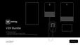
GM Energy V2H Bundle Installation Manual 78
Hub (bottom half, cover removed, bottom non-
backup with all wiring, terminations, and conduit
entry points visible)
Verify DC1 and Acrel meter wiring.
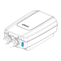
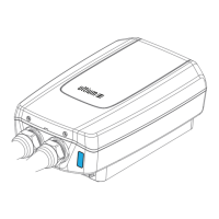
Hub (entire enclosure, two feet away with cover
removed)
Inverter (two feet away with cover removed, all
wiring terminations visible)
Verify conduit entry and wiring workmanship.
Verify terminations (L1/L1, comms, DC, solar,
PowerBank).
Inverter (closeup of wiring box, cover removed,
all wiring terminations visible)
Verify communication wiring, and DC, L1/L2,
and ESS/DSB communications terminations.
Electrical equipment (two feet away, showing
all electrical enclosures with covers on)
Multiple photos may be necessary if
equipment is in different locations.
Conduit workmanship, entries, and weep holes.
Equipment layout and clearances.
Must capture dark start, Inverter, Hub, MSP,
PowerBank, and subpanels; and conduit, and
conduit gutter boxes.
Gutter boxes (cover removed, showing all
wiring)
Verify NEC compliance and wiring workmanship.
Verify conduit workmanship.
Dark start (showing factory-installed cable to
Inverter)
Verify drain valve/mounting orientation.
Charger (middle cover, attached screws visible)
High chance of water ingress; verify middle
cover is attached properly.
Charger (cover removed, all wiring terminations
visible, showing conduit/wire entry points)
Verify wiring workmanship and terminations;
verify conduit entries.
Charger (cover removed, showing DIP switch
settings)
Refer to Section 4.2.
Verify DIP switch setting.
You must verify that the DIP switch setting does
not exceed capability of circuit per code
requirements
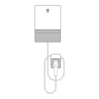
Charger (two feet away showing Charger and
holster, including conduit water drain)
Verify clearances and hardware mounting
workmanship.
Verify water egress method and conduit drain
tting.
Verify breaker and DIP switch settings are
correct.
Charger enclosure label (showing rating
setting)