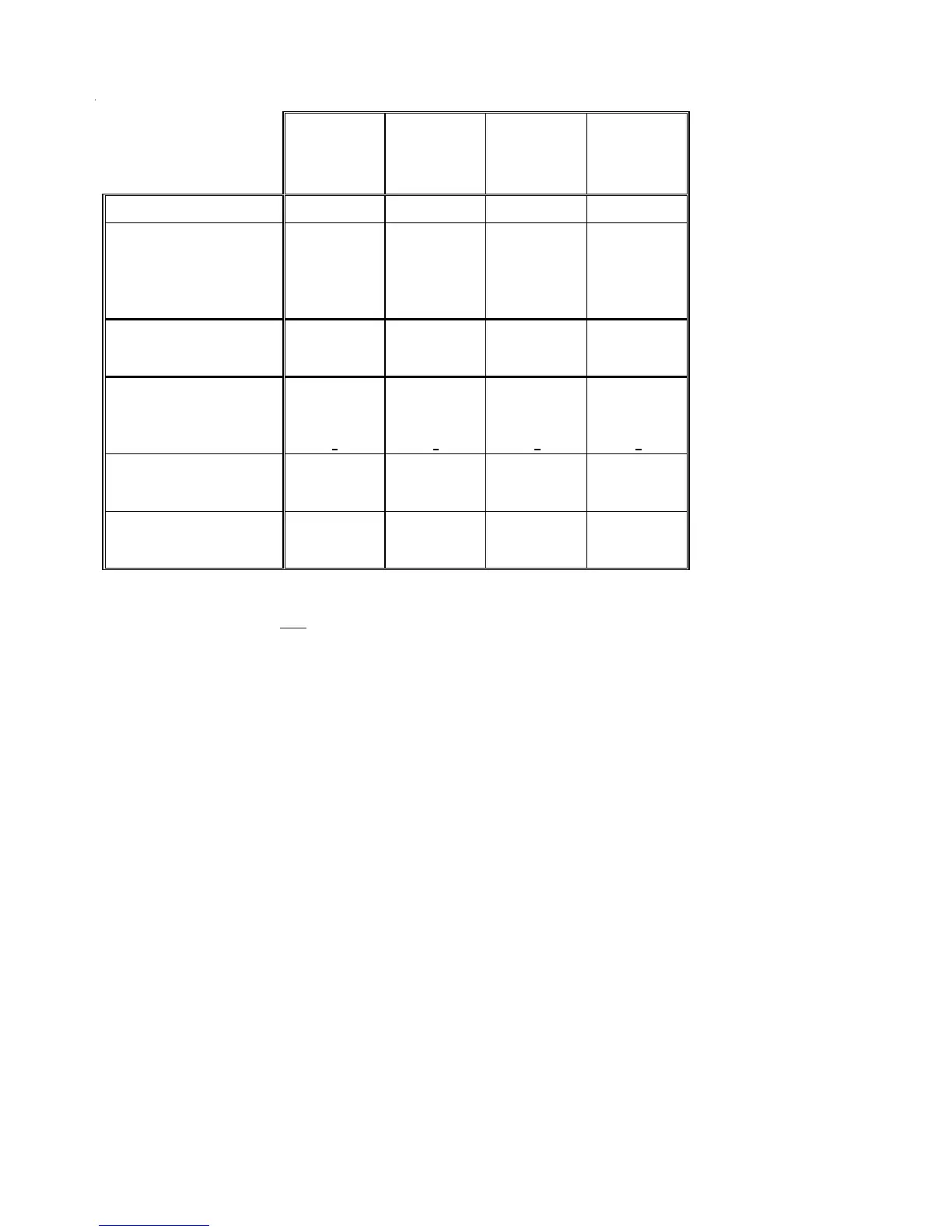
7
GSH130181B*
GSH130241B*
GSH130301B*
GSH130361B*
Cooling Capacity, BTUH 18,000 23,000 28,000 35,000
Compressor
R.L. Amps 6.2 9.2 10.8 12.2
L.R. Amps 35 43 60 73
Loss of Charge Pressure Switch
Open / Close 7 PSIG/25 PSIG 7 PSIG/25 PSIG 7 PSIG/25 PSIG 7 PSIG/25 PSIG
Condenser Fan Motor
Horsepower 1/6 1/6 1/6 1/4
F.L. Amps 1.1 1.1 1.1 1.5
Liquid Line, Inches O.D. 3/8" 3/8" 3/8" 3/8"
Suction Line, Inches O.D. 3/4" 3/4" 3/4" 7/8"
Refrigerant Charge 127 122 130 188
Design Subcooling Cooling (°F) 9 +
39 + 39 + 39 + 3
Power Supply 208/230-60-1 208/230-60-1 208/230-60-1 208/230-60-1
Minimum Circuit Ampacity
(1)
8.9 12.6 14.6 17
Maximum Overcurrent Device
(2 )
15 20 20 25
Electrical Conduit Size
Power Supply (Inches) 1/2 or 3/4 1/2 or 3/4 1/2 or 3/4 1/2 or 3/4
Approximate Shipping Weight 177 177 185 207
HEAT PUMP SPECIFICATIONS GSH130[18-36]1B*
(1)
Wire size should be determined in accordance with National Electrical Codes. Extensive wire runs will require larger wire sizes.
(2)
Maximum Overcurrent Protection: Must use fuses or HACR-type Circuit Breakers of the same size as noted.
NOTES:
* Always check the S&R plate for electrical data on the unit being installed.
* Installer will need to supply 7/8" to 1 1/8" adapters for suction line connections.
* Unit is charged with refrigerant for 15' of 3/8" liquid line. System charge must be adjusted per Installation Instructions Final Charge Procedure.
* Installation of these units that require a TXV Kit to be installed on the indoor coil: PLEASE NOTE: THE SPECIFIED TXV IS DETERMINED BY THE OUTDOOR UNIT
NOT THE INDOOR COIL
 Loading...