5. Fit and tighten the securing screw (A) to 1.3 Nm.
TM064082
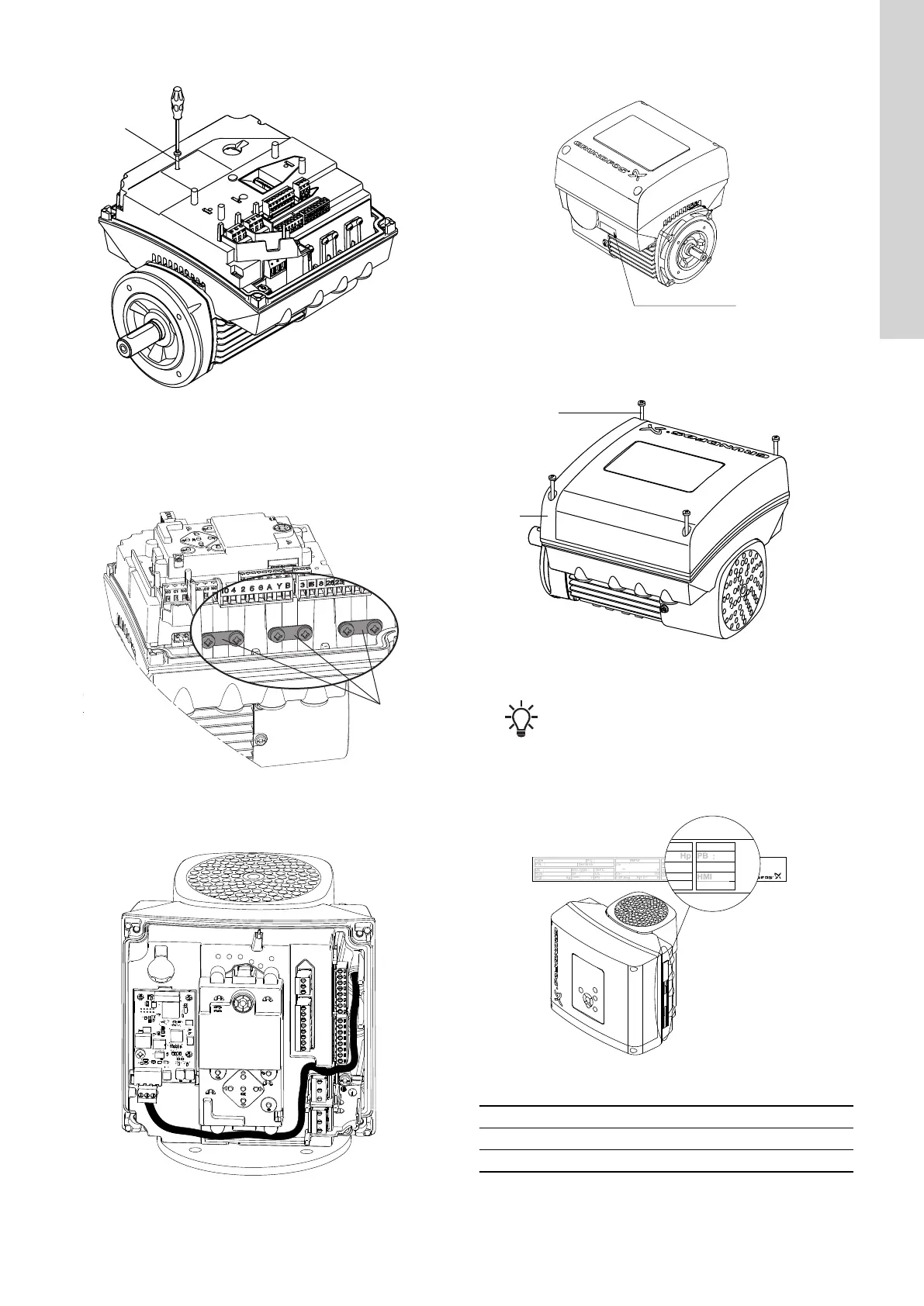
Fitting the securing screw
6. Make the electrical connections to the CIM module as described
in the instructions supplied with the module.
7. Connect the cable screens of the bus cables to earth via one of
the earth clamps (A).
TM064195
Connecting the cable screens to earth
8. Route the wires for the CIM module. See the example in figure
below.
TM064085
Example of wire routing
9. Fit the CIM cover.
10. If the CIM module is supplied with an FCC label, then place the
label on the terminal box.
TM057028
FCC label
11. Fit the terminal box cover (B) and cross-tighten the four
mounting screws (A) to 6 Nm.
TM081285
Fitting the terminal box cover
Make sure that the terminal box cover is aligned with
the control panel.
6. Identification of functional module
You can identify the fitted module on the motor nameplate.
Env.Type :
Serial no :
SF CL:
PF:
PB
FM
HMIEff
n max:
CIMWgt
:
DE
:
kg
NDE
:
T
amb
:
:
F AA
V
~
P.C.
:
Made in Hungary
OUTPUT
VARIANT
INPUT
TEFC
Type
:
P.N.
:
U
in
:
I
1/1
:
f
in
Hp
Hz
P2
I SF Amp:
rpm
: : :
:
:
:
:
Xxxxxxxxxxx
E.P. Motor
DK - 8850 Bjerringbro, Denmark
PB
FM
HMI
CIM
VARIANT
Hp
rpm
:
:
:
:
TM061889
Identification of functional module
Variant Description
FM 200 Standard functional module
FM 300 Advanced functional module
15
English (GB)