1. General information
Read this document before you install the product.
Installation and operation must comply with local
regulations and accepted codes of good practice.
1.1 Hazard statements
The symbols and hazard statements below may appear in Grundfos
installation and operating instructions, safety instructions and
service instructions.
DANGER
Indicates a hazardous situation which, if not avoided, will
result in death or serious personal injury.
WARNING
Indicates a hazardous situation which, if not avoided,
could result in death or serious personal injury.
CAUTION
Indicates a hazardous situation which, if not avoided,
could result in minor or moderate personal injury.
The hazard statements are structured in the following way:
SIGNAL WORD
Description of the hazard
Consequence of ignoring the warning
• Action to avoid the hazard.
1.2 Notes
The symbols and notes below may appear in Grundfos installation
and operating instructions, safety instructions and service
instructions.
Observe these instructions for explosion-proof products.
A blue or grey circle with a white graphical symbol
indicates that an action must be taken.
A red or grey circle with a diagonal bar, possibly with a
black graphical symbol, indicates that an action must not
be taken or must be stopped.
If these instructions are not observed, it may result in
malfunction or damage to the equipment.
Tips and advice that make the work easier.
2. Product introduction
2.1 Product description
The Hydro Multi-E system incorporates Grundfos CRE, CRIE,
CME-A or CME-I pumps with integrated frequency-controlled
single- or three-phase MGE motors and a breaker cabinet.
Grundfos Hydro Multi-E systems are designed for pressure
boosting of clean water in places such as:
• blocks of flats
• hotels
• hospitals
• schools
• office buildings.
The system adjusts its performance to the demand by cutting the
required number of pumps in or out and through parallel control of
the pumps in operation.
2.2 Intended use
The Hydro Multi-E system is a range of factory-assembled systems
ready for installation and operation.
The system maintains a constant pressure through continuous
variable adjustment of the speed of the connected pumps.
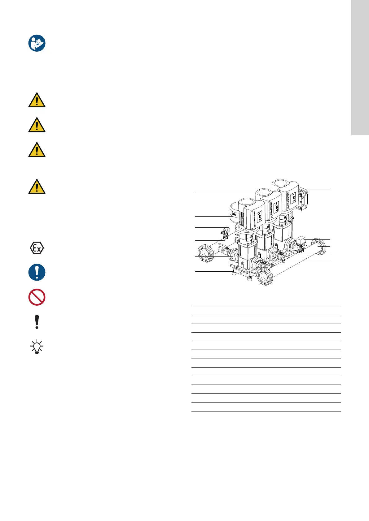
TM074824
Hydro Multi-E components
Pos. Description
1 Pump
2 Diaphragm tank
3 Pressure sensor and gauge
4 Outlet manifold
5 Non-return valve
6 Bent base frame or base frame C-profile
7 Breaker cabinet
8 Pressure switch or pressure sensor and gauge
9 Inlet manifold
10 Isolating valve
11 Nameplate
The breaker cabinet incorporates a main switch and circuit
breakers.
5
English (GB)