21. Technical data
21.1 Supply voltage
Hydro Multi-E with single-phase pumps
3 × 380-415 V ± 10 %, 50/60 Hz, N, PE.
Check that the supply voltage and frequency correspond to the
values stated on the nameplate.
Recommended fuse size
Motor size
[kW]
Min.
[A]
Max.
[A]
0.37 - 0.75 6 10
1.1 - 1.5 10 16
Standard as well as quick-blow or slow-blow fuses may be used.
Hydro Multi-E with three-phase pumps
3 × 380-480 V ± 10 %, 50/60 Hz, PE.
Check that the supply voltage and frequency correspond to the
values stated on the nameplate.
Recommended fuse size
Motor size
[kW]
Min.
[A]
Max.
[A]
0.37 - 1.1 6 6
1.5 6 10
2.2 6 16
3 10 16
4 13 16
5.5 16 32
7.5 20 32
11 32 32
Standard as well as quick-blow or slow-blow fuses may be used.
21.2 Leakage current
Hydro Multi-E with single-phase pumps
Motor size
[kW]
Number of pumps in
system
Leakage current
[mA]
0.37 - 1.5
2 < 7
3 < 10.5
4 < 14
The leakage currents are measured in accordance with EN
61800-5-1:2007.
Hydro Multi-E with three-phase pumps
Motor size
[kW]
Number of
pumps in system
Leakage current
[mA]
0.3 - 11
(supply voltage less than
400 V)
2 < 7
3 < 10.5
4 < 14
0.37 - 11
(supply voltage greater
than 400 V)
2 < 10
3 < 15
4 < 20
The leakage currents are measured in accordance with EN
61800-5-1:2007.
21.3
Torques
Terminal Thread size
Maximum torque
[Nm]
L1, L2, L3, L, N M4 1.8
NC, C1, C2, NO M2.5 0.5
1-26 and A, Y, B M2 0.5
21.4 Operating conditions
21.4.1 Ambient temperature during storage and transportation
Minimum -30 °C
Maximum +60 °C.
21.4.2 Ambient temperature during operation
Minimum 0°C
Maximum +40 °C.
21.4.3 Liquid temperature
+5 to +60 °C.
21.4.4 Installation altitude
Installation altitude is the height above sea level of the installation
site. Motors installed up to 1000 m above sea level can be loaded
100 %. The motors can be installed up to 3500 m above sea level.
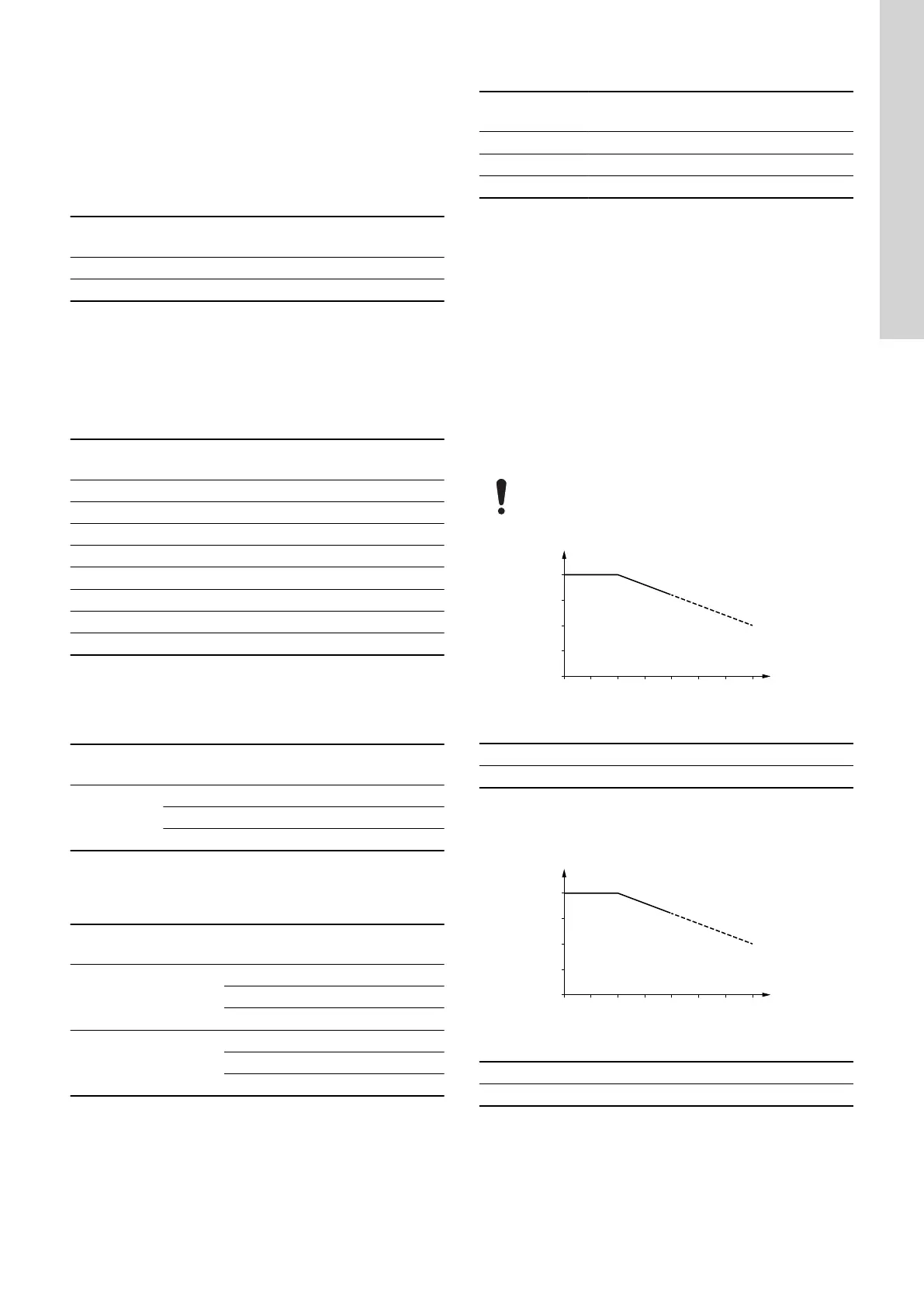
Motors installed more than 1000 m above sea level must
not be fully loaded due to the low density and consequent
low cooling effect of the air.
0
60
80
90
70
100
500 1000 1500 2000 2500 3000 3500
X
P2 [%]
TM055243
Motor output power in relation to altitude
Pos. Description
X Altitude [m]
In order to maintain the galvanic isolation and ensure correct
clearance according to EN 60664-1:2007, you must adapt the
supply voltage to the altitude:
0
60
80
90
70
100
500 1000 1500 2000 2500 3000 3500
X
P2 [%]
TM055243
Motor output power in relation to altitude
Pos. Description
X Altitude [m]
In order to maintain the galvanic isolation and ensure correct
clearance according to EN 60664-1:2007, you must adapt the
supply voltage to the altitude:
43
English (GB)