LIVE: You can connect supply voltages up to 250 VAC to the
output.
PELV: The output is galvanically separated from other
circuits. Therefore, you can connect the supply voltage or
protective extra-low voltage to the output as desired.
- Signal relay 2:
PELV: The output is galvanically separated from other
circuits. Therefore, you can connect the supply voltage or
protective extra-low voltage to the output as desired.
• Mains supply (terminals N, PE, L or L1, L2, L3, PE).
3
15
8
26
23
25
24
7
B
Y
6
5
2
4
10
A
AI2
GDS RX
GDS TX
GND
GENIbus A
GENIbus B
+5 V
+24 V
+24 V
GND
GENIbus Y
GND
+5 V
DI1
AI1
DI3/OC1
+24 V*
+
+
+24 V*/5 V*
+24 V*
+5 V*
NC
C2
NO
NC
C1
NO
+24 V*
+
+
+24 V*/5 V*
+24 V*
+24 V*
OC
DI
GND
TM053510
Connection terminals, CME pump (optional for CRE, CRIE,
CRNE, SPKE and MTRE pumps)
* If you use an external supply source, there must be a connection
to GND.
Terminal
Type Function
NC
Normally closed
contact
Signal relay 1
(LIVE or PELV)
C1 Common
NO
Normally open
contact
NC
Normally closed
contact
Signal relay 2
(PELV only)
C2 Common
NO
Normally open
contact
10 DI3/OC1
Digital input/output, configurable
Open collector: Max. 24 V
resistive or inductive
4 AI1
Analog input:
0-20 mA / 4-20 mA
0.5 - 3.5 V / 0-5 V / 0-10 V
2 DI1 Digital input, configurable
5 +5 V
Supply to potentiometer and
sensor
6 GND Ground
A GENIbus, A GENIbus, A (+)
Y GENIbus, Y GENIbus, GND
B GENIbus, B GENIbus, B (-)
3 GND Ground
15 +24 V Supply
Terminal Type Function
8 +24 V Supply
26 +5 V
Supply to potentiometer and
sensor
23 GND Ground
25 GDS TX Grundfos Digital Sensor output
24 GDS RX Grundfos Digital Sensor input
7 AI2
Analog input:
0-20 mA / 4-20 mA
0.5 - 3.5 V / 0-5 V / 0-10 V
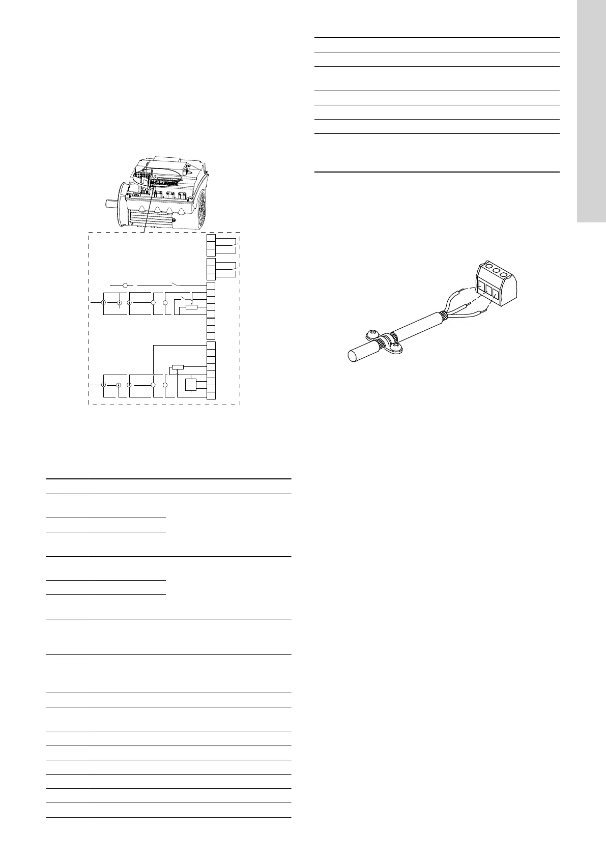
4.8 Signal cables
• Use screened cables with a cross-sectional area of minimum
0.5 mm
2
and maximum 1.5 mm
2
for the external on/off switch,
digital inputs, setpoint and sensor signals.
• Connect the screens of the cables to the frame at both ends.
The screens must be as close as possible to the terminals.
TM021325
Stripped cable with screen and wire connections
• Always tighten screws for frame connections whether a cable is
fitted or not.
• The wires in the motor terminal box must be as short as
possible.
13
English (GB)