3
15
8
26
23
25
24
7
21
20
22
B
Y
6
5
2
4
10
A
+24 V*
1
14
9
12
17
19
11
18
+24 V*
+
+24 V*
OC
DI
+24 V*/5 V*
+24 V*
+
+
+
+24 V*/5 V*
+24 V*
+24 V*
+
+
+24 V*/5 V*
+24 V*
+5 V*
AI2
GDS RX
GDS TX
GND
GENIbus A
GENIbus B
+5 V
+24 V
+24 V
GND
GENIbus Y
GND
+5 V
DI1
AI1
DI3/OC1
LiqTec
AI3
GND
DI2
LiqTec
GND
AO
Pt100/1000
Pt100/1000
DI4/OC2
GND
+24 V*
OC
DI
GND
NC
C2
NO
NC
C1
NO
+5 V*
TM053509
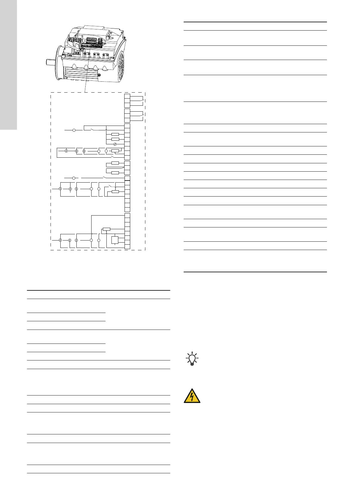
Connection terminals, CRE, CRIE and CRNE pumps
* If you use an external supply source, there must be a connection
to GND.
Terminal
Type Function
NC
Normally closed
contact
Signal relay 1
(LIVE or PELV)
C1 Common
NO Normally open contact
NC
Normally closed
contact
Signal relay 2
(PELV only)
C2 Common
NO Normally open contact
18 GND Ground
11 DI4/OC2
Digital input/output,
configurable
Open collector: Max. 24 V
resistive or inductive
19 Pt100/1000 input 2 Pt100/1000 sensor input
17 Pt100/1000 input 1 Pt100/1000 sensor input
12 AO
Analog output:
0-20 mA / 4-20 mA
0-10 V
9 GND Ground
14 AI3
Analog input:
0-20 mA / 4-20 mA
0-10 V
1 DI2 Digital input, configurable
Terminal Type Function
21 LiqTec sensor input 1
LiqTec sensor input
(white conductor)
20 GND
Ground (brown and black
conductors)
22 LiqTec sensor input 2
LiqTec sensor input
(blue conductor)
10 DI3/OC1
Digital input/output,
configurable
Open collector: Max. 24 V
resistive or inductive
4 AI1
Analog input:
0-20 mA / 4-20 mA
0.5 - 3.5 V / 0-5 V / 0-10 V
2 DI1 Digital input, configurable
5 +5 V
Supply to potentiometer and
sensor
6 GND Ground
A GENIbus, A GENIbus, A (+)
Y GENIbus, Y GENIbus, GND
B GENIbus, B GENIbus, B (-)
3 GND Ground
15 +24 V Supply
8 +24 V Supply
26 +5 V
Supply to potentiometer and
sensor
23 GND Ground
25 GDS TX
Grundfos Digital Sensor
output
24 GDS RX Grundfos Digital Sensor input
7 AI2
Analog input:
0-20 mA / 4-20 mA
0.5 - 3.5 V / 0-5 V / 0-10 V
4.7.2 Connection terminals, CME pumps
The CME pump has these connections:
• two analog inputs
• two digital inputs or one digital input and one open-collector
output
• Grundfos Digital Sensor input and output
• two signal relay outputs
• GENIbus connection.
See the figure below for connection terminals of CME pump.
Digital input 1 is factory-set to be the start-stop input when
open circuit results in stop. A jumper has been factory-
fitted between terminals 2 and 6. Remove the jumper if
digital input 1 is to be used as external start-stop or any
other external function.
DANGER
Electric shock
Death or serious personal injury
‐ Make sure that the wires to be connected to the
connection groups are separated from each other by
reinforced insulation in their entire lengths.
• Inputs and outputs
All inputs and outputs are internally separated from the mains-
conducting parts by reinforced insulation and galvanically separated
from other circuits. All control terminals are supplied by protective
extra-low voltage (PELV) to ensure protection against electric
shock.
• Signal relay outputs
- Signal relay 1:
12
English (GB)