11.8 Predefined setpoints
You can set and activate seven predefined setpoints by combining
the input signals to digital inputs 2, 3 and 4. See the table below.
Set the digital inputs 2, 3 and 4 to Predefined setpoints if all seven
predefined setpoints are to be used. You can also set one or two of
the digital inputs to Predefined setpoints but this limits the number
of predefined setpoints available.
Digital inputs
Setpoint
2 3 4
0 0 0 Normal setpoint or stop
1 0 0 Predefined setpoint 1
0 1 0 Predefined setpoint 2
1 1 0 Predefined setpoint 3
0 0 1 Predefined setpoint 4
1 0 1 Predefined setpoint 5
0 1 1 Predefined setpoint 6
1 1 1 Predefined setpoint 7
0: Open contact
1: Closed contact
Example
The figure below shows how you can use the digital inputs to set
seven predefined setpoints. Digital input 2 is open and digital inputs
3 and 4 are closed. If you compare with the table above, you can
see that Predefined setpoint 6 is activated.
0
1
2
3
4
5
6
7
Dl4
SP
a
SP7
SP6
SP5
SP4
SP3
SP2
SP1
SP
n
Stop
Dl3
Dl2
TM064269
Principle sketch showing how predefined setpoints function
Pos. Description
SP Setpoint
DI Digital input
SP
a
Actual setpoint
SP
n
Normal setpoint
If all digital inputs are open, the pump stops or runs at the normal
setpoint. Set the desired action with Grundfos GO or with the
advanced control panel.
Factory settings
See section Factory settings.
Related information
21.6 Factory settings
11.9
Alarm log
This menu contains a list of logged alarms from the product. The
log shows the name of the alarm, when the alarm occurred and
when it was reset.
11.10
Warning log
This menu contains a list of logged warnings from the product. The
log shows the name of the warning, when the warning occurred and
when it was reset.
11.11 Multi-pump setup
The multi-pump function enables the control of two pumps
connected in parallel without the use of external controllers. The
pumps in a multi-pump system communicate with each other via the
wireless GENIair connection or the wired GENI connection.
You can set a multi-pump system via the master pump, which is the
first selected pump.
If two pumps in the system are configured with an outlet-pressure
sensor, they can all function as master pumps and take over the
master pump function if the other should fail. This provides
additional redundancy in the multi-pump system.
11.11.1 Cascade
Cascade operation is possible with two to four pumps of same size
and type connected in parallel. Each pump requires a non-return
valve in series with the pump.
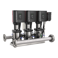
Hydro Multi-E maintains a constant pressure through continuously
variable adjustment of the speed of the pumps connected. It adjusts
its performance to the demand through cutting in or out the required
number of pumps and through parallel control of the pumps in
operation.
11.11.2 Setting up a multi-pump system
You can setup a multi-pump system in the following ways:
• Grundfos GO and wired pump connection
• Advanced control panel and wired pump connection
• Grundfos GO and wireless pump connection
• Advanced control panel and wireless pump connection.
See step-by-step descriptions below.
Grundfos GO with wired pump connection (bus cable)
1. Power on the pumps.
2. Establish contact to the first pump with Grundfos GO.
3. Set the needed analog and digital inputs according to the
connected equipment and the required functionality.
4. Assign a GENI address starting with (1) on the first pump, (2) on
the next, etc.
5. Disconnect Grundfos GO from the pump.
6. Connect to the next pump with Grundfos GO and follow steps
3-5.
7. Do the previous steps for the rest of the pumps in the system.
8. When the last pump is configured, connect Grundfos GO to
pump 1 again.
9. Select the Assist menu and choose Setup of multi-pump
system.
10. Select the multi-pump function (in this case cascade).
11. Press [>] to continue.
12. Select the communication method to be used between the
pumps (in this case Bus cable).
13. Press [>] to continue.
14. The system will scan the bus and list all the additional pumps
(not pump 1) automatically.
15. When all pumps are listed, press Confirm, and the system will
initiate and be ready to start.
Advanced control panel with wired pump connection (bus
cable)
1. Power on the pumps.
2. On pump 1, use the advanced control panel and go to the
setting menu.
3. Set the needed analog and digital inputs according to the
connected equipment and the required functionality.
4. Assign a GENI address starting with (1) on the first pump, (2) on
the next, etc.
5. Move to the next pump.
6. Use the advanced control panel and follow steps 3-5.
32
English (GB)
 Loading...
