Possible functions, Digital input/output 4
Function if input
See details in section Digital
input.
Function if output
See details in section Signal
relay 1 and 2 (Relay outputs).
Not active
External stop
Min.
Max.
User-defined speed
External fault
Alarm resetting
Dry running
Accumulated flow
Predefined setpoint digit 3
Not active
Ready
Alarm
Operation
Pump running
Warning
Limit 1 exceeded
Limit 2 exceeded
Activation delay (only for input)
Select the activation delay (T1).
This is the time between the digital signal and the activation of the
selected function.
Range: 0 to 6000 seconds.
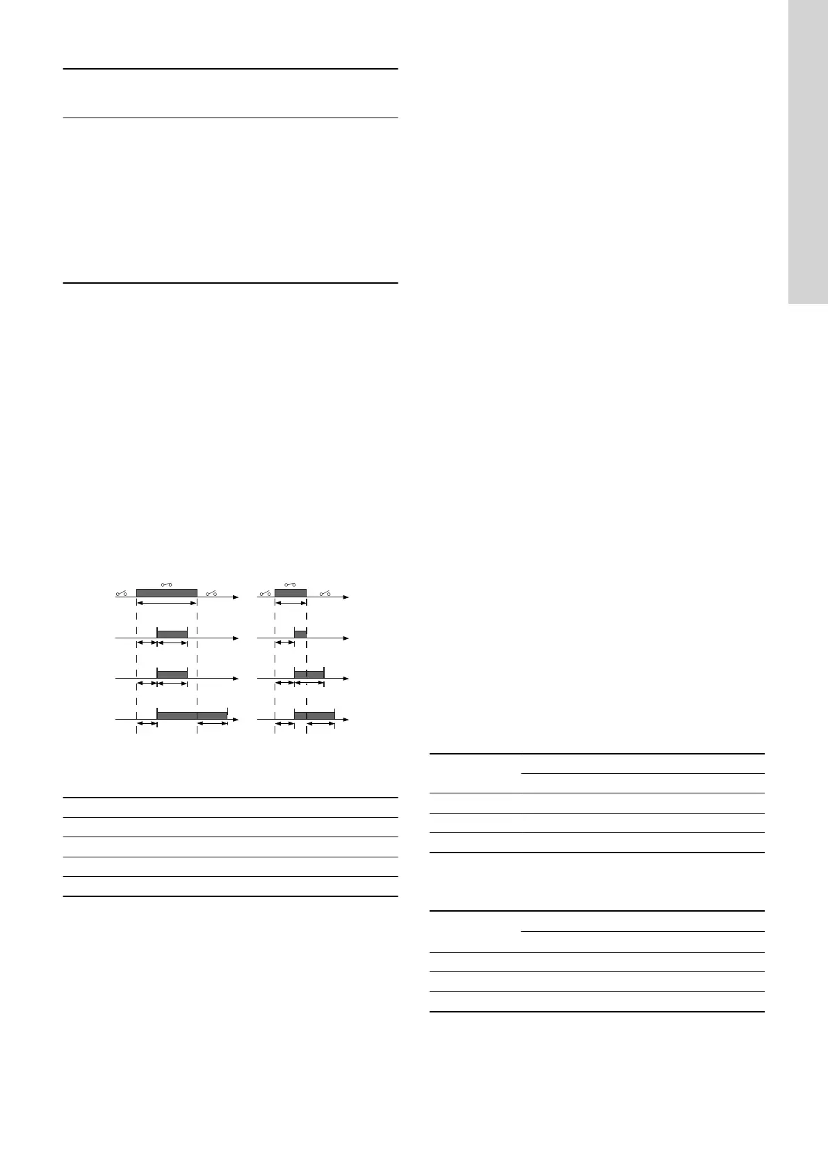
Duration timer mode (only for input)
Select the duration timer mode.
• Not active
• Active with interrupt (mode A)
• Active without interrupt (mode B)
• Active with after-run (mode C).
Select the duration time (T2).
This is the time which, together with the mode, determines how long
the selected function is active.
Range: 0 to 15,000 seconds.
T input
DI
A
B
C
T input > T1 + T2 T input < T1 + T2
T1 T2
T1 T2
T1 T1 T2T2
T1
T1
T input
T2
TM064949
Duration timer function of digital inputs
Pos. Description
A Mode A
B Mode B
C Mode C
DI Digital input
Factory settings
See section Factory settings.
Related information
11.5 Signal relay 1 and 2 (Relay outputs)
17. Digital input
21.6 Factory settings
11.5
Signal relay 1 and 2 (Relay outputs)
The pump incorporates two signal relays for potential-free signals.
For further information, see section Signal relays.
Function
You can configure the signal relays to be activated by one of the
following incidents:
• Not active.
• Ready. The pump can be running or is ready to run and no
alarms are present.
• Alarm. There is an active alarm, and the pump is stopped.
• Operating (Operation). Operating equals Running but the
pump is still in operation when the pump is stopped due to low
flow. See low-flow detection in section Stop function.
• Running (Pump running). The pump is running.
• Warning. There is an active warning.
• Limit 1 exceeded. When this function is activated, the signal
relay is activated. See section Limit-exceeded function.
• Limit 2 exceeded. When this function is activated, the signal
relay is activated. See section Limit-exceeded function.
• External fan control (Control of external fan). When you
select External fan control, the relay is activated if the internal
temperature of the motor electronics reaches a preset limit
value.
Factory settings
See section Factory settings.
Related information
10.5 Stop function
10.8 Limit-exceeded function
16. Signal relays
21.6 Factory settings
11.6 Analog output
The analog output enables the reading of certain operating data to
external control systems.
To set the analog output, make the settings below.
Output signal
• 0-10 V
• 0-20 mA
• 4-20 mA.
Function of analog output
• Actual speed
Signal range
[V, mA]
Actual speed [%]
0 100 200
0-10 V 0 V 5 V 10 V
0-20 mA 0 mA 10 mA 20 m
4-20 mA 4 mA 12 mA 20 mA
The reading is a percentage of the rated speed.
• Actual value
Signal range
[V, mA]
Actual value
Sensor
min
Sensor
max
0-10 V 0 V 10 V
0-20 mA 0 mA 20 mA
4-20 mA 4 mA 20 mA
The reading is a percentage of the range between the minimum and
maximum value.
• Resulting setpoint
29
English (GB)