Signal range
[V, mA]
Resulting setpoint [%]
0 100
0-10 V 0 V 10 V
0-20 mA 0 mA 20 mA
4-20 mA 4 mA 20 mA
The reading is a percentage of the external setpoint range.
• Motor load
Signal range
[V, mA]
Motor load [%]
0 100
0-10 V 0 V 10 V
0-20 mA 0 mA 20 mA
4-20 mA 4 mA 20 mA
The reading is a percentage of the range between 0 and 200 % of
the maximum permissible load at the actual speed.
• Motor current
Signal range
[V, mA]
Motor current [%]
0 100 200
0-10 V 0 V 5 V 10 V
0-20 mA 0 mA 10 mA 20 mA
4-20 mA 4 mA 12 mA 20 mA
The reading is a percentage of the range between 0 % and 200 %
of the rated current.
• Limit 1 exceeded and Limit 2 exceeded
Signal range
[V, mA]
Limit-exceeded function
Output not active Output active
0-10 V 0 V 10 V
0-20 mA 0 mA 20 mA
4-20 mA 4 mA 20 mA
This function is typically used for monitoring of secondary
parameters in the system. If the limit is exceeded, an output, a
warning or an alarm is activated.
• Flow rate
Signal range
[V, mA]
Flow rate [%]
0 100 200
0-10 V 0 V 5 V 10 V
0-20 mA 0 mA 10 mA 20 mA
4-20 mA 4 mA 12 mA 20 mA
The reading is a percentage of the range between 0 and 200 % of
the nominal flow.
Factory settings
See section Factory settings.
Related information
21.6 Factory settings
11.7
External setpoint function
You can influence the setpoint with an external signal via
• one of the analog inputs
• one of the Pt100/1000 inputs if an advanced functional module
(FM 300) is fitted,
Before you can enable the function, you must set one of
the analog inputs or Pt100/1000 inputs to External
setpoint function.
See sections Analog inputs and Pt100/1000 inputs.
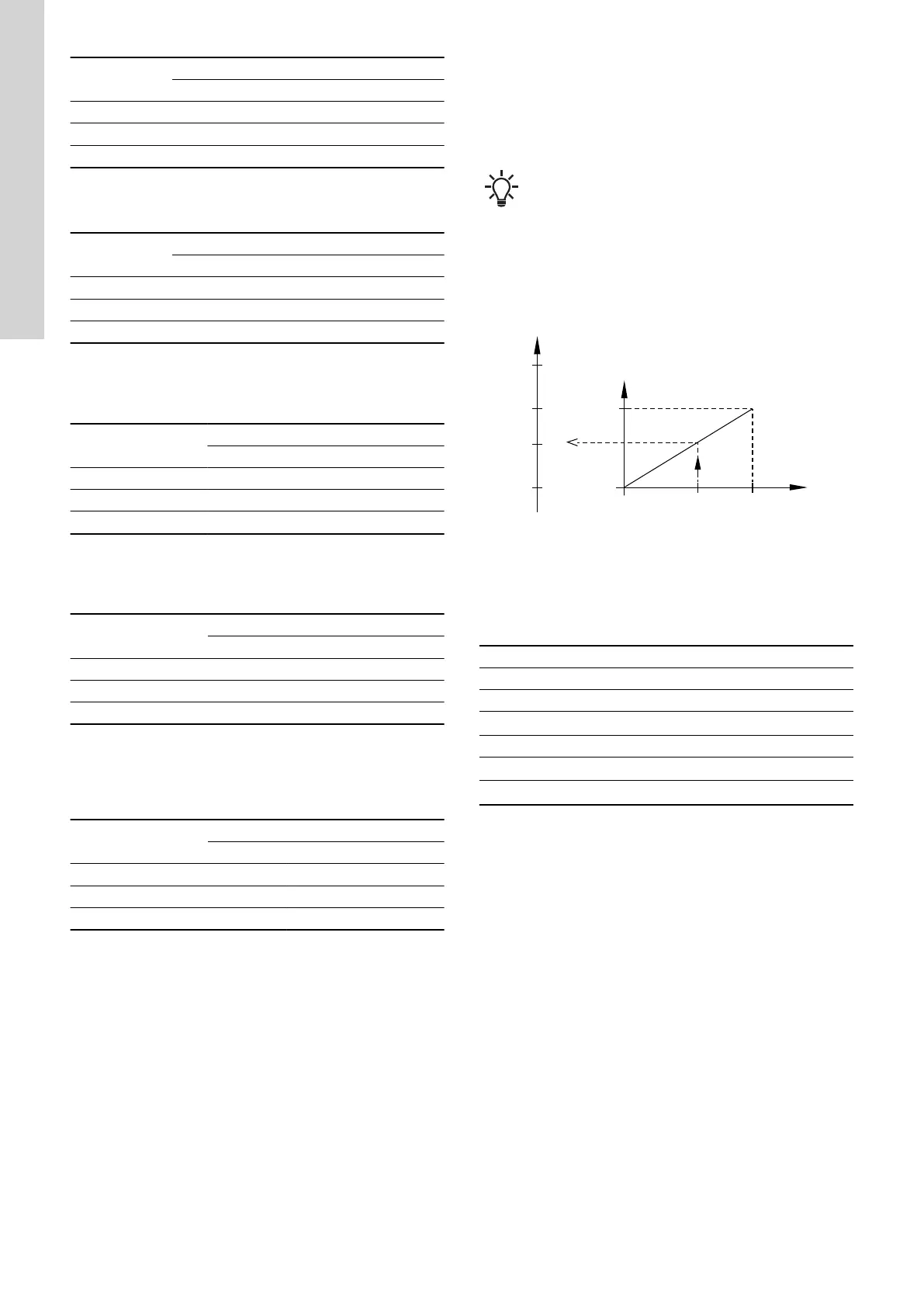
Example with constant pressure with linear influence
Actual setpoint: actual input signal × (setpoint - sensor min.) +
sensor min.
At a sensor min. of 0 bar, a setpoint of 2 bar and an external
setpoint of 60 %, the actual setpoint is 0.6 × (2 - 0) + 0 = 1.2 bar.
100
0
100 %
0
1.2
2
[bar]
0
3.5 V0.5
5 V0
10 V0
20 mA0
20 mA4
-50 204
SP
S
min
SP
a
A
B
S
max
°C
TM064165
Example of setpoint influence with sensor feedback
Pos. Description
A Actual input signal (60 %)
B External setpoint signal
S
max
Sensor max.
SP Setpoint
SP
a
Actual setpoint
S
min
Sensor min.
Example with constant curve with linear influence
Actual setpoint: actual input signal × (setpoint - user-set minimum
speed) + user-set minimum speed.
At a user-set minimum speed of 25 %, and a setpoint of 85 % and
an external setpoint of 60 %, the actual setpoint is 0.60 × (85 - 25) +
25 = 61 %.
30
English (GB)