13. Protective functions
It is important that any protective function, for example dry-running
protection or external start/stop that is detected via a digital input, is
connected to and configured on all the pumps with an outlet-
pressure sensor.
If an additional sensor is used, for example the limit-exceeded
function or setpoint influence, this sensor must also be connected to
all pumps with an outlet-pressure sensor. Alternatively, an additional
sensor per pump with an outlet-pressure sensor can be installed.
13.1 Dry-running protection
Hydro Multi-E must be protected against dry running.
Types of dry-running protection:
• a pressure switch or an inlet pressure sensor is factory-fitted to
the inlet manifold. See sections Pressure switch and Inlet
pressure sensor.
• a level switch fitted in a water tank (optional). See section Level
switch.
Related information
13.1.3 Inlet pressure sensor
13.1.1 Pressure switch
13.1.2 Level switch
13.1.1
Pressure switch
The Hydro Multi-E can be fitted with an adjustable pressure switch
as dry-running protection. The pressure switch is fitted to the inlet
manifold.
If the inlet pressure is below the lower switching point, the
system cannot start.
If the pressure switch has stopped the system during
operation due to the inlet pressure being too low, the inlet
pressure must increase to a pressure that is higher than
the setting of the upper switching point before the system
can restart.
If necessary, adjust the lower switching point by turning screw A
and adjust the upper switching point to a value higher than the
lower switching point by turning screw B. See figure below.
Do not set the lower switching point to a value below the
minimum inlet pressure. See section Minimum inlet
pressure.
TM058436
Adjustment of switching points
Pos. Description
A Low pressure SP
B High pressure SP
Related information
21.4.7 Minimum inlet pressure
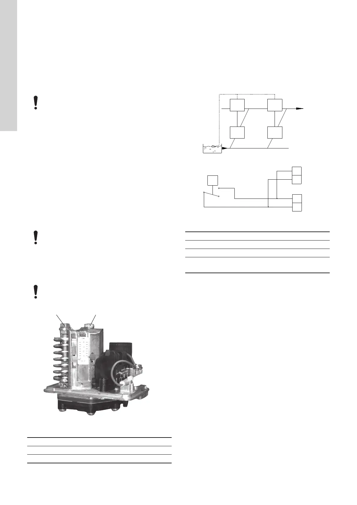
13.1.2
Level switch
If there is no inlet pressure, the system can be optionally fitted with
a level switch, either from factory or after delivery. The level switch
can for instance monitor the water level in a tank connected to the
inlet manifold and must be connected to terminal 3 and 10 in all
pumps. See Advanced functional module (FM 300) in section Inlet
pressure sensor.
Furthermore, the digital input must be configured with Grundfos GO
to detect dry running.
The system starts up automatically if it has been stopped due to dry
running. It can be changed to manually restart with Grundfos GO.
TM065328
Level switch connected to each pump
Pos. Description
A Pump 1
B Pump 2
C
3: GND (frame)
10: Digital input
Related information
13.1.3 Inlet pressure sensor
36
English (GB)