13.1.3 Inlet pressure sensor
The Hydro Multi-E system can be fitted with one or two inlet
pressure sensors, either from factory or after delivery. The sensor
can monitor the pressure in the inlet manifold and must be
connected to one of the analog input. See Advanced functional
module (FM 300) in this section.
From factory the system has been set to start automatically if it has
been stopped due to dry running. It can be changed to manually
restart with Grundfos GO or via advanced control panel.
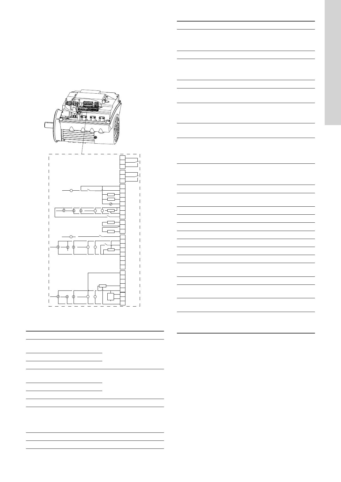
Advanced functional module (FM 300)
3
15
8
26
23
25
24
7
21
20
22
B
Y
6
5
2
4
10
A
+24 V*
1
14
9
12
17
19
11
18
+24 V*
+
+24 V*
OC
DI
+24 V*/5 V*
+24 V*
+
+
+
+24 V*/5 V*
+24 V*
+24 V*
+
+
+24 V*/5 V*
+24 V*
+5 V*
AI2
GDS RX
GDS TX
GND
GENIbus A
GENIbus B
+5 V
+24 V
+24 V
GND
GENIbus Y
GND
+5 V
DI1
AI1
DI3/OC1
LiqTec
AI3
GND
DI2
LiqTec
GND
AO
Pt100/1000
Pt100/1000
DI4/OC2
GND
+24 V*
OC
DI
GND
NC
C2
NO
NC
C1
NO
+5 V*
TM053509
* If an external supply source is used, there must be a connection to
GND.
Terminal
Type Function
NC
Normally closed
contact
Signal relay 1
(LIVE or SELV)
C1 Common
NO Normally open contact
NC
Normally closed
contact
Signal relay 2
(SELV only)
C2 Common
NO Normally open contact
18 GND Ground
11 DI4/OC2
Digital input/output,
configurable.
Open collector: Maximum 24
V resistive or inductive
19 Pt100/1000 Pt100/1000 sensor input 2
17 Pt100/1000 Pt100/1000 sensor input 1
Terminal Type Function
12 AO
Analog output:
0-20 mA / 4-20 mA
0-10 V
9 GND Ground
14 AI3
Analog input:
0-20 mA / 4-20 mA
0-10 V
1 DI2 Digital input, configurable
21 LiqTec
LiqTec sensor input 1
(white conductor)
20 GND
Ground
(brown and black
conductors)
22 LiqTec
LiqTec sensor input 2
(blue conductor)
10 DI3/OC1
Digital input/output,
configurable.
Open collector: Maximum 24
V resistive or inductive
4 AI1
Analog input:
0-20 mA / 4-20 mA
0.5 - 3.5 V / 0-5 V / 0-10 V
2 DI1 Digital input, configurable
5 +5 V
Supply to potentiometer and
sensor
6 GND Ground
A GENIbus, A GENIbus, A (+)
Y GENIbus, Y GENIbus, GND
B GENIbus, B GENIbus, B (-)
3 GND Ground
15 +24 V Supply
8 +24 V Supply
26 +5 V
Supply to potentiometer and
sensor
23 GND Ground
25 GDS TX
Grundfos Digital Sensor
output
24 GDS RX
Grundfos Digital Sensor
input
7 AI2
Analog input:
0-20 mA / 4-20 mA
0.5 - 3.5 V / 0-5 V / 0-10 V
37
English (GB)