4.4 Electrical installation
Carry out the electrical connection according to local regulations.
Check that the supply voltage and frequency correspond to the
values stated on the nameplate.
DANGER
Electric shock
Death or serious personal injury
‐ Switch off the power supply and make sure that the
power supply cannot be accidentally switched on.
‐ Make sure that the wires to be connected to the
connection groups are separated from each other by
reinforced insulation in their entire lengths.
WARNING
Electric shock
Death or serious personal injury
‐ Installation must be carried out by qualified personnel,
and according to local regulations.
If the power supply cable is damaged, it must be replaced by the
manufacturer, the manufacturer's service partner or a similarly
qualified person.
The user or the installer is responsible for the installation of correct
earthing and protection according to local regulations. All operations
must be carried out by a qualified electrician.
The system must be stationary and installed
permanently. Furthermore, connect the system permanently to the
power supply.
Carry out the earth connection as duplicate conductors.
If the system cannot be installed with the supply disconnecting
device located minimum 0.6 m above service level according to EN
60204-1 paragraph 5.3.4, install the system with an external "supply
disconnecting device" made according to EN 60204-1, paragraph
5.3.2. The system must be provided with a means permitting it to be
locked in OFF (isolated) position.
4.4.1
Protection against electric shock, indirect contact
DANGER
Electric shock
Death or serious personal injury
‐ Connect the motor to protective earth and protect
against indirect contact according to local regulations.
Protective-earth conductors must always have a green, or green/
yellow (PE) colour marking.
Protection against mains voltage transients
The motor is protected against mains voltage transients in
accordance with EN 61800-3.
Motor protection
The motor requires no external motor protection. The motor
incorporates thermal protection against slow overloading and
blocking.
4.4.2
Insulation resistance
Do not measure the insulation resistance of motor
windings or an installation incorporating motors with
integrated frequency converters using high-voltage
megging equipment as this may damage the built-in
electronics.
4.5 Mains supply
Check that the supply voltage and frequency correspond to the
values stated on the nameplate.
Use dedicated IT network motors if the system is supplied
through an IT network. Contact Grundfos.
The wires in the breaker cabinet must be as short as possible.
Excepted from this is the separated earth conductor which must be
so long that it is the last one to be disconnected in case the cable is
inadvertently pulled out of the cable entry.
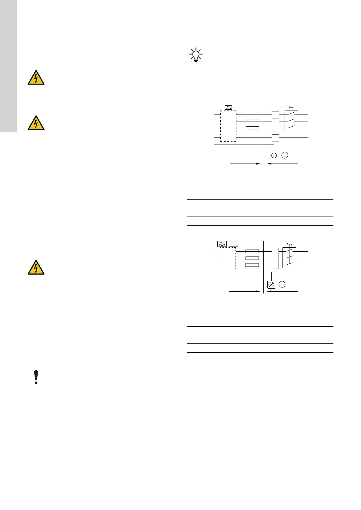
For maximum backup fuse, see section Supply voltage.
A
N
N
B
PE
L3
L3
L2
L2
L1
L1
ELCB
(GFCI)
TM024547
Example of a mains-connected Hydro Multi-E with backup fuses
and additional protection (applies only for systems with single-
phase motors)
Pos. Description
A Installation in building
B Breaker cabinet
For maximum backup fuse, see section Supply voltage.
A
ELCB
(GFCI)
PE
L3
L2
L1
L3
L2
L1
B
TM024546
Example of a mains-connected Hydro Multi-E with backup fuses
and additional protection (applies only for systems with three-
phase motors)
Pos. Description
A Installation in building
B Breaker cabinet
Related information
21.1 Supply voltage
10
English (GB)