500 2500 35001500
500
480
460
440
420
380
400
X
Y
IE5
TM069866
Supply voltage for three-phase motor in relation to altitude
Pos. Description
Y Supply voltage [V]
X Altitude [m]
0
200
220
230
210
250
500 1500 2500 3500
2
240
1
IE5
TM069867
Supply voltage for single-phase motor in relation to altitude
Pos. Description
1 Supply voltage [V]
2 Altitude [m]
21.4.5 Humidity
Maximum 95 %.
21.4.6
Maximum operating pressure
See system nameplate.
21.4.7
Minimum inlet pressure
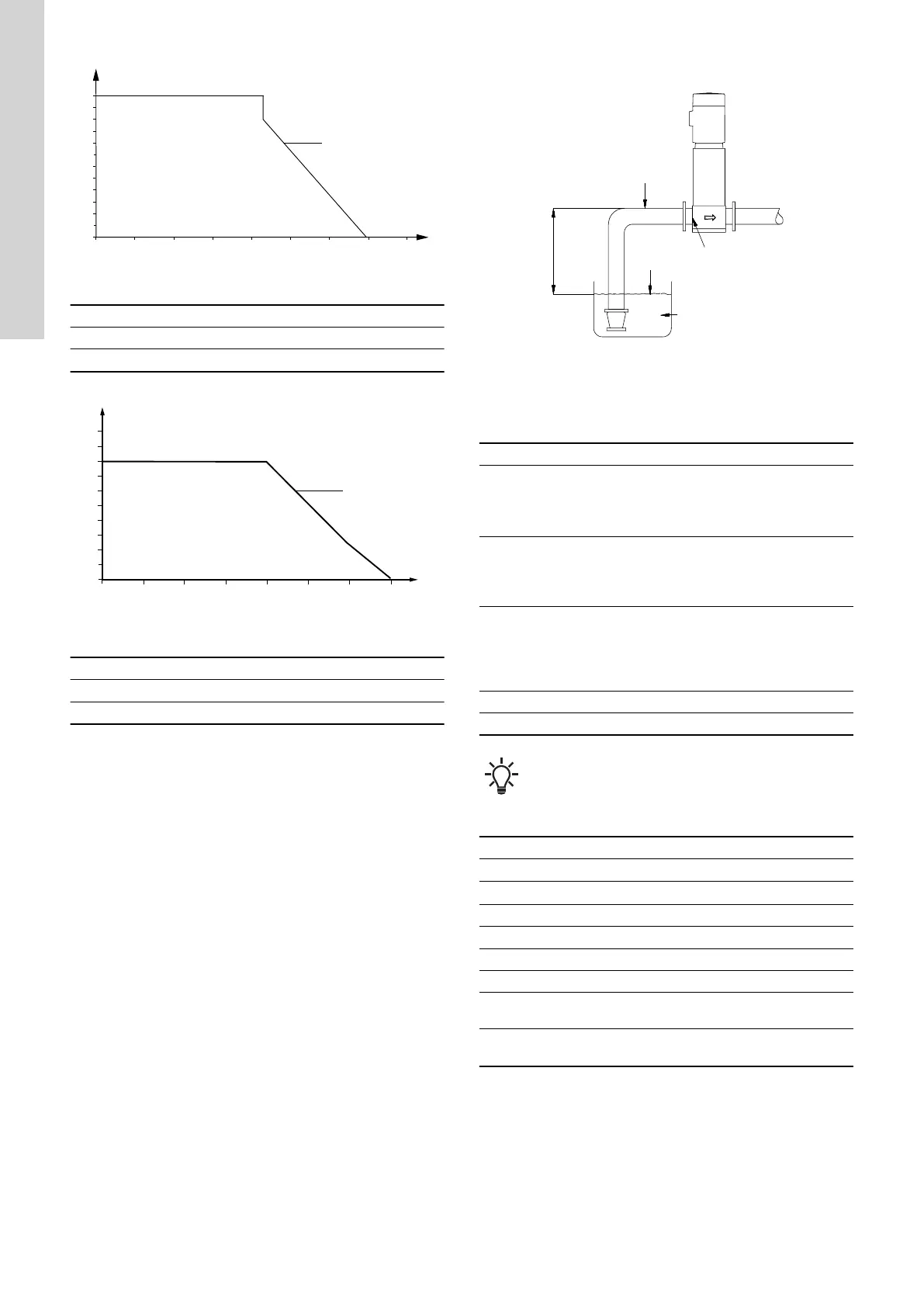
TM020118
Parameters for the calculation of minimum inlet pressure
The minimum inlet pressure "H" in metres of head required to avoid
cavitation in the pumps can be calculated as follows:
H = pb × 10.2 - NPSH - Hf - Hv - Hs
pb =
Barometric pressure in bar. Barometric pressure can be
set to 1 bar.
In closed systems, p
b
indicates the system pressure in
bar.
NPSH =
Net Positive Suction Head in metres of head
The NPSH value can be read from the NPSH curve at
the highest flow which the individual pump will be
delivering.
Hf =
Friction loss in inlet manifold in metres of head at the
highest flow the individual pump will be delivering.
Note: If a non-return valve is installed on the inlet side
of the pump, the friction loss in the valve must be
added. See the manufacturer's data.
Hv = Vapour pressure in metres of head.
Hs = Safety margin of min. 0.5 metres of head.
In some regions, the system is available with a low inlet
manifold which makes it more suitable for suction lift
operation. Contact Grundfos for further information.
Example
pb
= 1 bar
Pump type = CRE 15, 50 Hz
Flow rate =
15 m
3
/h
NPSH = 1.2 metres head
Hf = 3.0 metres head
Liquid temperature = +60 °C
Hv = 2.1 metres head
H =
pb × 10.2 - NPSH - Hf - Hv - Hs [metres
head]
H =
1 × 10.2 - 1.2 - 3.0 - 2.1 - 0.5 = 3.4 metres
head
This means that each pump can operate at a suction lift of
maximum 3.4 metres head.
Pressure calculated in bar: 3.4 × 0.0981 = 0.33.
Pressure calculated in kPa: 3.4 × 9.81 = 33.4.
21.4.8
Maximum inlet pressure
The maximum inlet pressure must not exceed 8 bar.
However, the actual inlet pressure plus pressure when the pump is
operating against a closed valve must always be lower than the
maximum operating pressure.
44
English (GB)