RCS User Manual
55
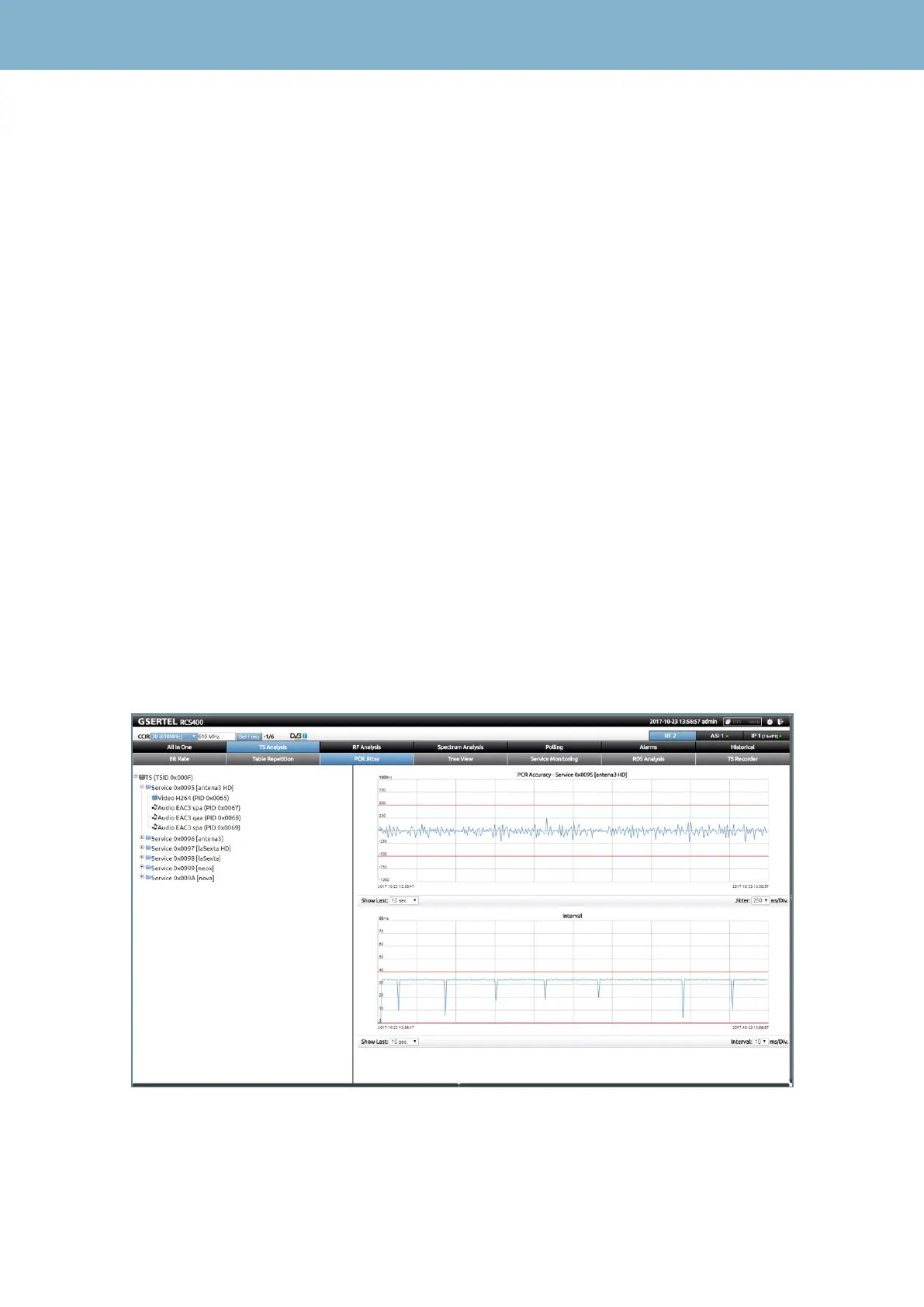
3.4.- PCR Jitter -Option 902512 only for RCS100 and RCS400-
This feature shows two graphs that represent the PCR jitter and the PCR interval of a selected
MPEG Video.
On the left side of the screen, there is a list with all the services of the channel. The user must select
a MPEG Video to see the PCR jitter and PCR interval graphs on the right side of the screen.
The PCR (Program Clock Reference) is a timestamp included in some particular packets of the
MPEG Transport Stream that is used for the video decoder to be able to reconstruct the clock with
which it was generated the video stream and thus have the right temporal references .
The PCR jitter is a measure of the frequency stability of PCR timestamps. A high jitter may cause
the decoder is unable to reconstruct the clock correctly and so, the video may not decoded properly.
The standard indicates that jitter must be less than + - 500 ns The upper graph of the picture below
represents the time evolution of the jitter corresponding to the video selected from the left list, as
well as two red lines, which correspond to the upper and lower thresholds above and below which
the PCR jitter alarm is triggered.
The PCR interval is a measure of the range of arrival of the packets carrying the PCR time
references. The standard indicates that interval must be <40 ms. If it is higher, it is possible that the
video decoder is unable to reconstruct the video generation clock correctly. The lower graph of the
picture below represents the time evolution of the abovementioned intervals corresponding to the
video selected from the left list, as well as one red line, which corresponds to the upper thresholds
above which the PCR interval alarm is triggered.
The user can select the time interval to be displayed, as well as the scale of the graphs.
 Loading...