© Guldmann GB/US-09/2016 • #550376_3
113
SERVICE AND REPAIR
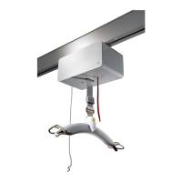
Reconnect the motorunit to the PC board according to the
electrical diagram (page 155).
Remove the protective tape from the circuit board sup-
ports, make sure that the cables are behind the PC board
and place the PC board in the middle of the cover.
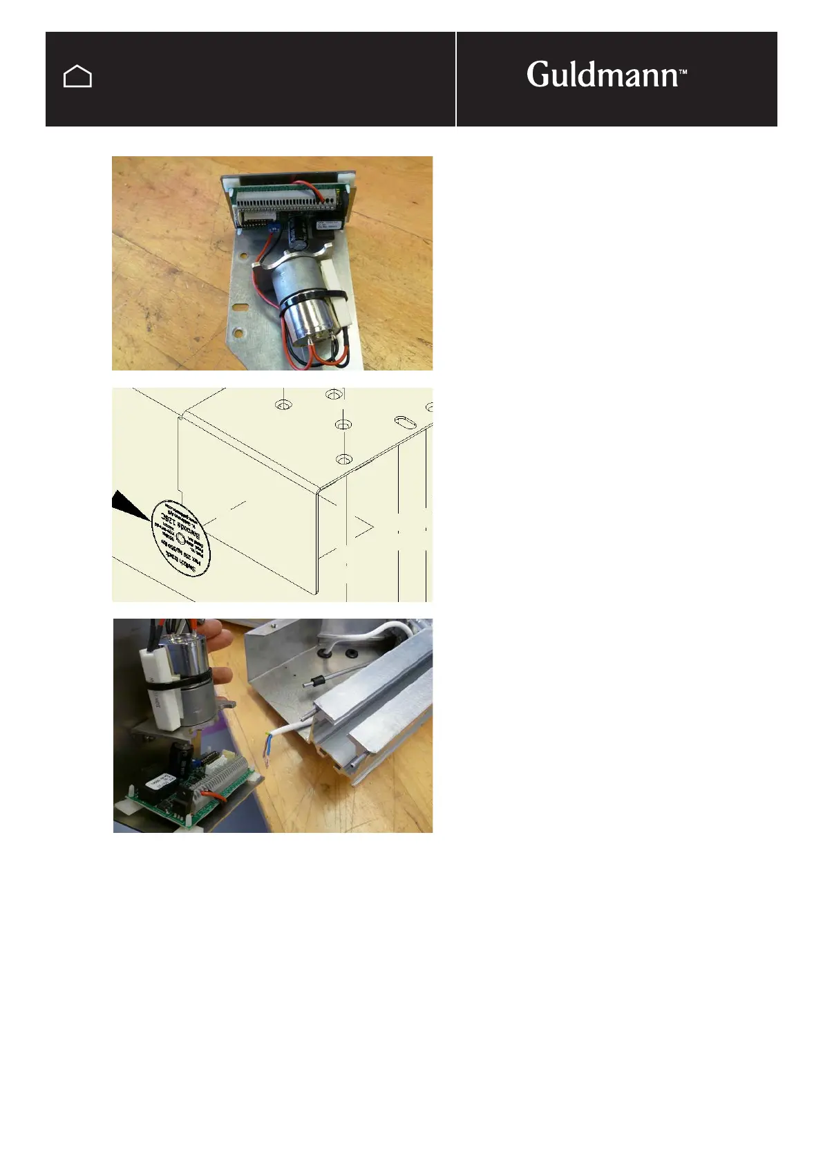
The spare label for switch track GH with the barcode is
removed from the pocket inside the motorhousing and
placed on the end of the top cover.
Re-connect the wires from the transformer according to the
electrical diagram (page 155).
Fasten the transformer cables with the strain relief – leaving
only the shortest possible cable.
Place the cover correct and test that the function on of the
switch track by pulling the turning arm from side to side.
When switching the activation arm shall move from side to
side with a distinct movement. If this is not the case, please
follow the list until correct function is obtained.
a) Control that the change arm and the turning arm are
connected correct.
b) Control that the activation plate and the activation arm
are connected correct. The activation arm must be
placed between the legs of the activation plate.
c) Make sure that the sleeve is placed right above the
motor mounting plate, if not move the sleeve and the
two locking washers to make sure the sleeve is placed
correct and re-install the cover.
d) The sleeve must obtain a slight pressure against the
motor mounting plate. If this is not the case, slightly
bend the activation arm to ensure a slight pressure and
test the function of the switch track.
Re-install the cover and test again.
Switch track GH
 Loading...