© Guldmann GB/US-09/2016 • #550376_3
45
SERVICE AND REPAIR
GH3
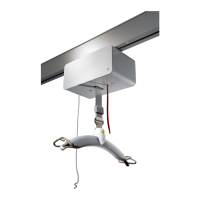
Replacing the Auxiliary motor PCB
The Motor auxiliary PCB is connected to the leader motor
safety PCB via a green strip connector.
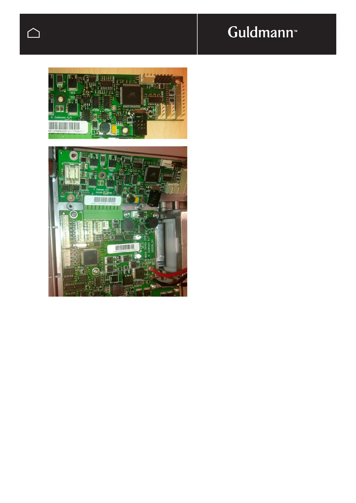
Disconnect any wires from the PCB remembering were they
are connected. Taking a photo is a good way to record this,
also see wiring diagram at back of manual.
Undo and take out the screws (Torx 10) attaching the PCB
to the cooling plate, you will need to loosen some of the
screws on the motor safety PCB as well to remove the aux-
iliary PCB from the connector.
Connect the new PCB to the connector strip and refix the
screws to the cooling plate.
Reconnect wires and reassemble hoist leaving the battery’s
until last.
NOTE:
It is important to register all PCB exchanges on the
Guldmann traceability web site.