© Guldmann GB/US-09/2016 • #550376_3
158
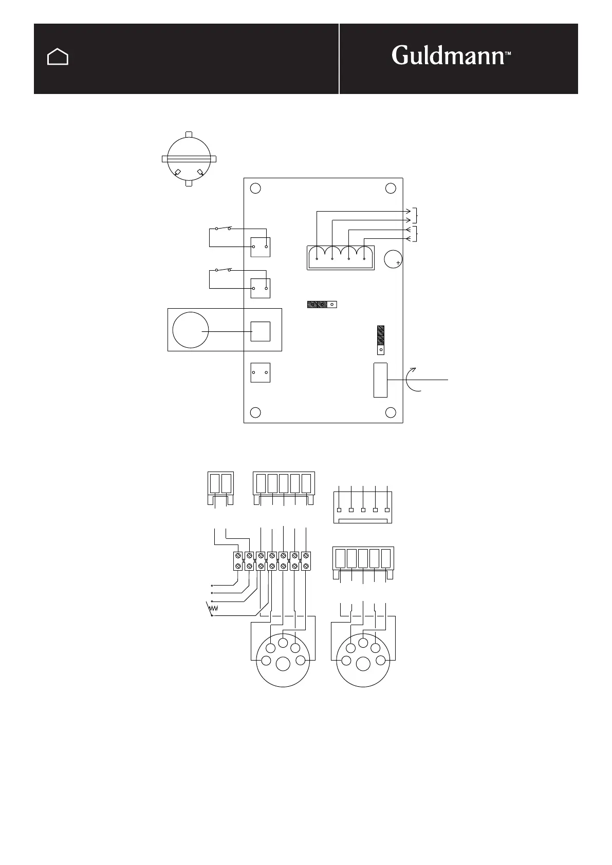
TECHNICAL DRAWINGS
Electrical diagram
Turn tabel GH
from handswitch
5 pole 180º fitted
on the back
White
Brown
Brown
Green
3
2
1
4
Male plug
on the back
5 pole 180º fitted
PO 10 A
for handswitch
5 pol plug
5 pol plug
Female plug
Male Molex
Female Molex
PC board:
2
Yellow
Gray
White
3
Green
Brown
4
1
Diode (+)
GND (÷)
Shift
24V + DC
Not in use
5
5
Yellow
Gray
24V DC
X2
X2X5
24v AC
Switch
LS1
1
1 1 5 3 4
2
2 2
1 5 3 4 2
X1
2
1
X3
1
4
24V AC
1
LS2
LS2 LS1
2
X4
X5
GND
GND
starting position after a specified period
ASTABLE: Turn table returns automatically to
Brown
Black
Blue
Blue
Green
Blue
Yellow
Orange
Red
switch
Hand
Max.
Min.
10 SEC.
Timer
Astable
SW1
OFF
LOCK
ON
BIST.
ASS.
Eg.: Bistable
combi lock
End stop 1
End stop 2
SW2
1
2
1
2
Motor
P010A
Endstop LS2 (pos. x4) tobe replaced by endstop LS1 (pos. x3)
and motor lines GREEN/BLACK in pos. x5 are replaced.
CHANGE OF STARTING POSITION OF TURN TABLE