Page 94
The COM LED indicates the modules CAN communication status.
On Solid = Module on-line
Flashing slow (2Hz) = CAN bus okay, but the module is not receiving messages from the Foam Con-
troller.
Flashing fast (8Hz) = CAN bus error, no communications.
Gray connector (this connector is the same between the old and new motor drivers)
Mating connector: Deutsch DT06-12SA GRAY
Mating sockets: Deutsch 0462-201-16141
Gold mating sockets: Deutsch 0462-201-1631
Recommended wire gage: 16-20 AWG
Wedge lock: W12S
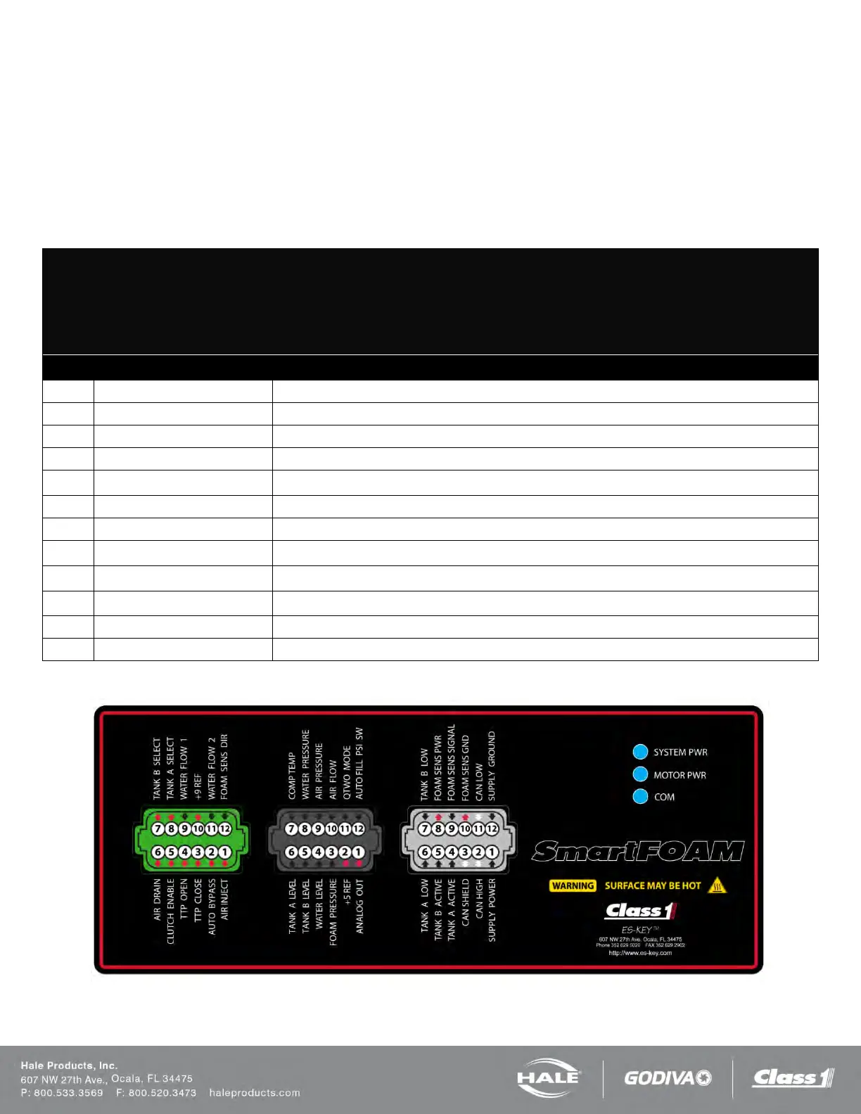
PIN CIRCUIT DESCRIPTION
1 SYS POWER (INPUT) – Battery voltage (+9VDC…+32VDC)
(DATA) – SAE J1939 CAN 2.0B, 250Kbits/s
(DATA) – SAE J1939 CAN 2.0B, 250Kbits/s
4 TANK A ACTIVE (INPUT) – Positive polarity
5 TANK B ACTIVE (INPUT) – Positive polarity
6 TANK A LOW (INPUT) – Positive polarity
7 TANK B LOW (INPUT) – Positive polarity
8 FOAM SENS PWR (OUTPUT) – Reference voltage for foam sensor (battery power)
9 FOAM SENS SIG (INPUT) – Positive pulse signal
10 FOAM SENS GND (OUTPUT) – Battery ground
11 CAN LOW (DATA) – SAE J1939 CAN 2.0B, 250Kbits/s
12 SYS GROUND (INPUT) – Battery ground
Figure 83: 610-00044 pinouts