Page 93
Distribution Box
(Early and Pre 2017)
The Distribution Box (part of the pump/motor assembly) con-
trols the speed of the pump/motor based on commands from
the SmartFOAM controller display. The distribution box also
receives the signal from the foam feedback sensor, low tank
sensor(s), and tank selector and relays that information back
to the SmartFOAM controller display.
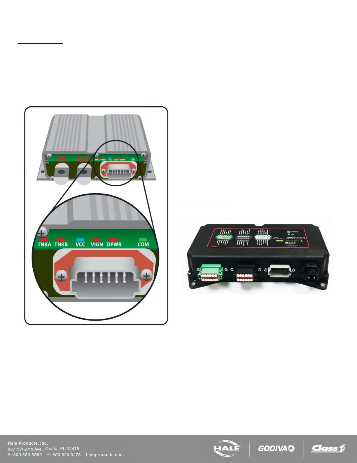
Figure 81: Distribution Box LEDs
The distribution box contains six internal LEDs to help with
diagnostics (refer to Figure 70: Distribution Box LEDs).
❑ TNKA is illuminated when the tank selector is set to
“tank A”. This is based on a physical input into pin 4
of the gray connector on the front of the distribution
box. (When the TNKA and TNKB LEDs are OFF the
system is in FLUSH mode).
❑ TNKB is illuminated when the tank selector is set to
“tank B”. This is based on a physical input into pin 5
of the gray connector on the front of the distribution
box. (When the TNKA and TNKB LEDs are OFF the
system is in FLUSH mode).
❑ VCC is illuminated when power and ground are ap-
plied to the distribution box pins 1 and 12. This indi-
cates that the internal 5 volt regulator is functioning
for the internal components.
❑ VIGN is illuminated when power and ground are ap-
plied to the distribution box pins 1 and 12. This indi-
cates that system power and ground are recognized
within the unit.
❑ DPWR is illuminated when the “IN” power stud is en-
ergized with system voltage. This power is required
to drive the motor attached to the pump.
❑ COM is illuminated when the distribution box is com-
municating with the SmartFOAM controller display
via the CAN. This LED with be flashing if there is a
CAN communication problem and it cannot com-
municate with the SmartFOAM controller display.
If no tank selector (MST, MDTII, ADT) is used a connector
plug is installed to connector C8 to lock the system in the
Tank A mode (Figure 45 and Figure 46). Removing this plug
or disconnecting the tank selector
cable and places the sys-
tem in the FLUSH mode.
Distribution Box
(Late 2017 and Newer)
Figure 82: 610-00044 New Distribution Box
The distribution box was upgraded Fall 2017 to 610-00044.
This new distribution box has improved protection against
overcurrent. There are three inputs (green, black, and grey),
but only the grey is utilized for foam units. The black con-
nector is power. There are three standalone indicator lights
on the top of the case:
❑ SYSTEM PWR is illuminated when the “IN” power
stud is energized with system voltage. This power is
required to drive the motor attached to the pump.
❑ MOTOR PWR is illuminated when there is power
output to the foam motor.
❑ COM is illuminated when the distribution box is com-
municating with the SmartFOAM controller display
via the CAN. This LED with be flashing if there is a
CAN communication problem and it cannot com-
municate with the SmartFOAM controller display.