Interconnecting cables
The connections between modules are made using pre-fabricated cables.
At each end of the cable there is a coloured label. This will match coloured connectors on the modules.
The cables are keyed to only fit the correct connectors.
In two or three station installations, the cable between station control panels must be installed the correct
way. The white connector is fitted to the first station control panel in the chain and the green connector
fitted to the next station control panel.
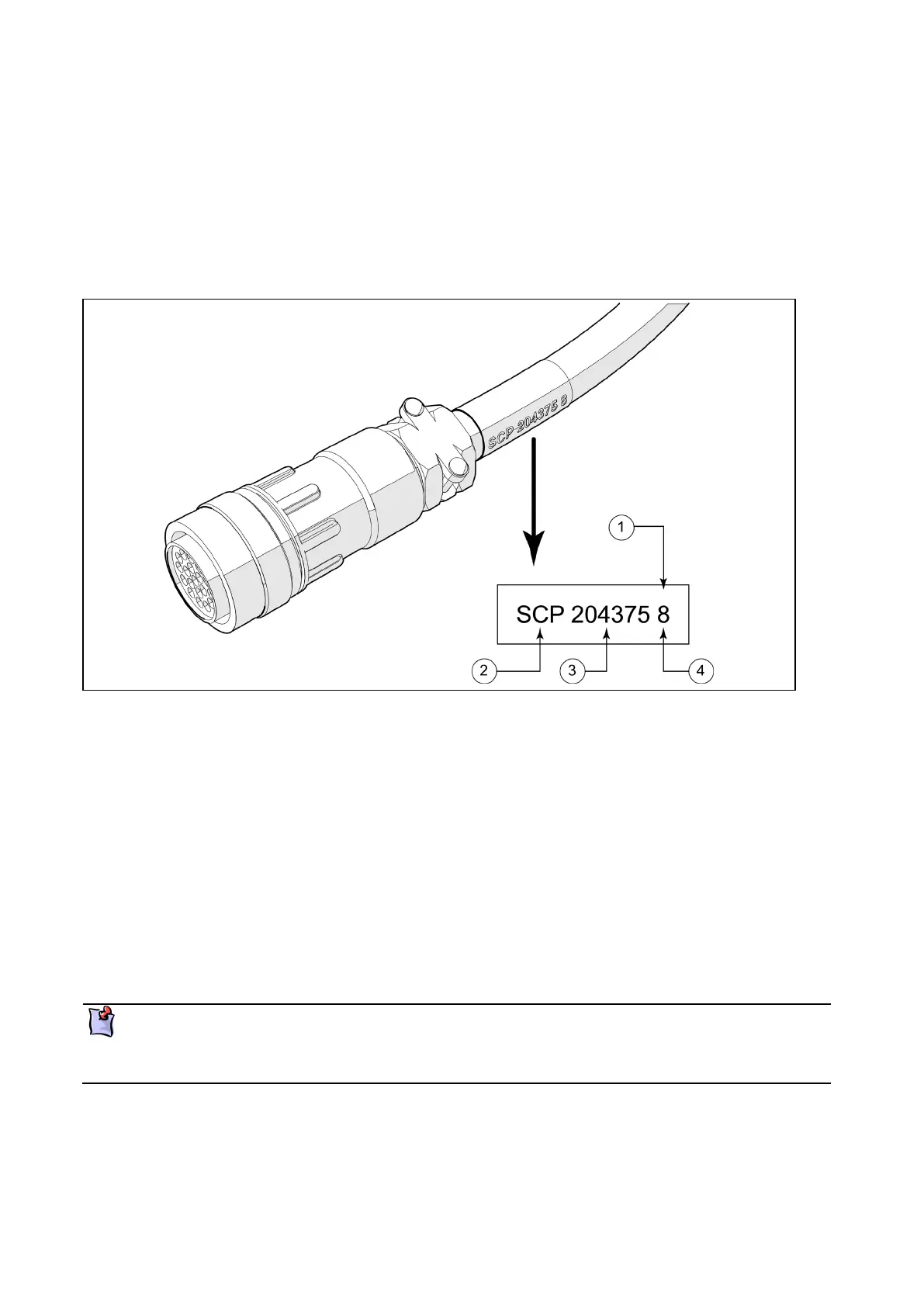
Figure 5: Typical cable labelling
Coloured label (label colours can be, yellow, white, green, blue, black)
The module that this connector plugs into (Station Control Panel in this example)
Note the following when installing cables:
Install the cables on cable trays or enclosed ducts.
Do not install heavy cables on top of lighter cables.
Do not mix signal cables with power cabling.
Apply cable ties approximately every 400mm.
Keep cables parallel, and avoid unnecessary crossovers.
Avoid sharp edged cable ties or unprotected metal.
Securely attach the cables at the module connectors.
For detailed connection information refer to vessel configuration schemas available on the
Hamilton web site.
Drawing views are looking from the rear of the modules
 Loading...