GPS antenna weight (excluding mounting
adaptor): 0.75 kg.
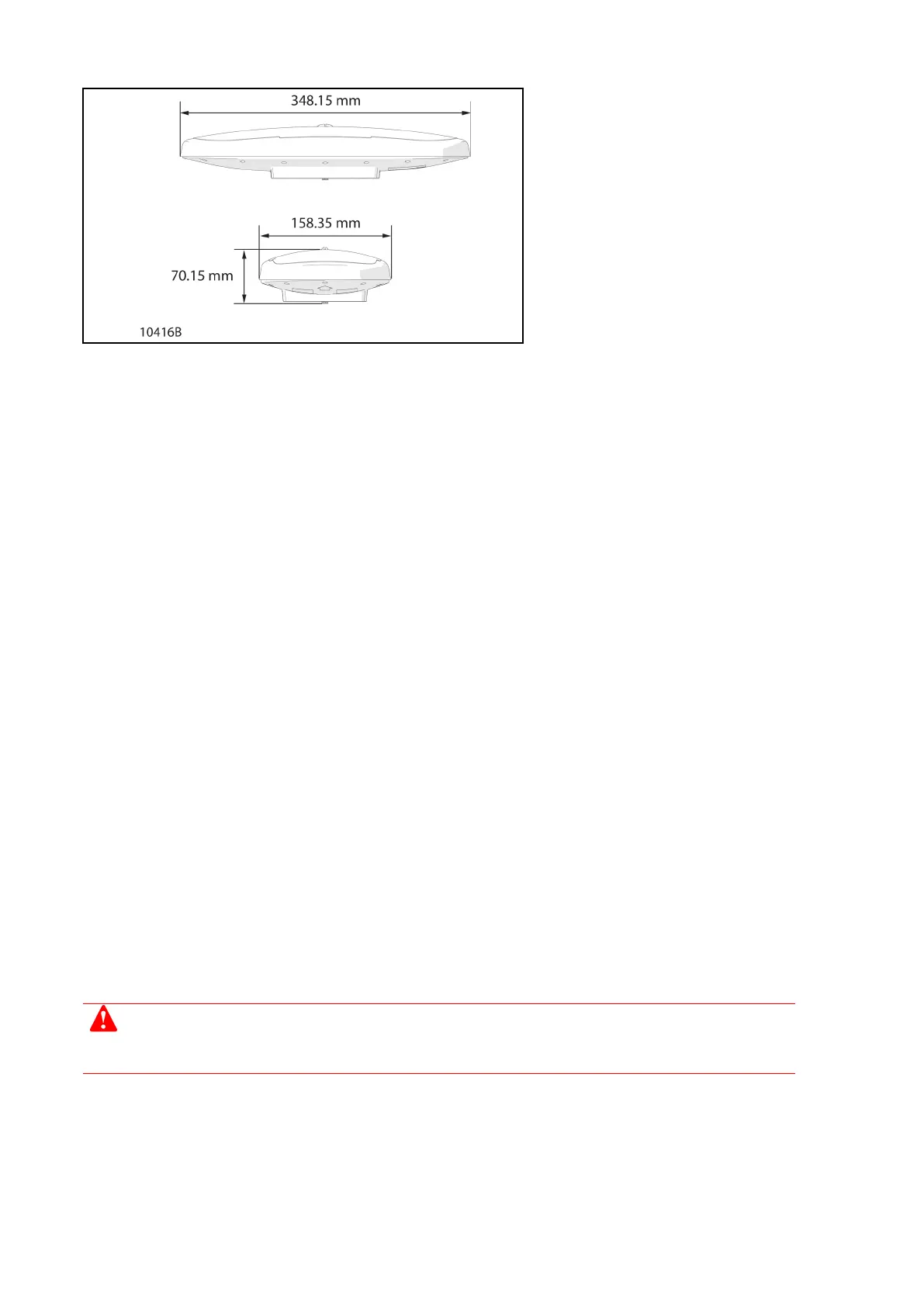
Figure 28: GPS antenna dimensions
(without mounting adapter)
Module inputs and outputs
Refer to the appropriate vessel wiring schematics for wiring information.
Module inputs and outputs
Output - Throttle:
blue ARROW provides normal and backup throttles.
If the engine does not support a backup throttle, a changeover relay must be provided to select between
normal and backup throttle demand.
This is a voltage free contact that will short to ground when in normal mode, and float high when in
backup mode.
The relay coil is connected between battery supply + and the normal/backup control line.
Normal throttle is connected to the NO contact.
Backup throttle is connected to the NC contact.
Output - Engine start interlock:
blue ARROW provides an engine start interlock.
This is a voltage free contact signal which is shorted to ground when blue Arrow is in control of the
vessel.
This signal will inhibit engine starting when it is floating.
A relay must be provided with the coil connected between battery supply + and the engine start interlock
line
The NO contacts must be in series with the engine start solenoid.
In the unlikely event of a complete control system failure, the engine start interlock will
prevent the engine from starting.
This will leave a single jet vessel with no means of propulsion.
A bypass switch must be fitted across the engine start interlock relay to allow the engine to start.
Alternatively, a relay with a manually lockable test option (for example, Omron MY2IN ) can be used as the
engine start interlock relay.
Refer to the appropriate engine schematics for details.
This bypass switch is optional for twin jet vessels.
 Loading...