Connect the sensor to a cable
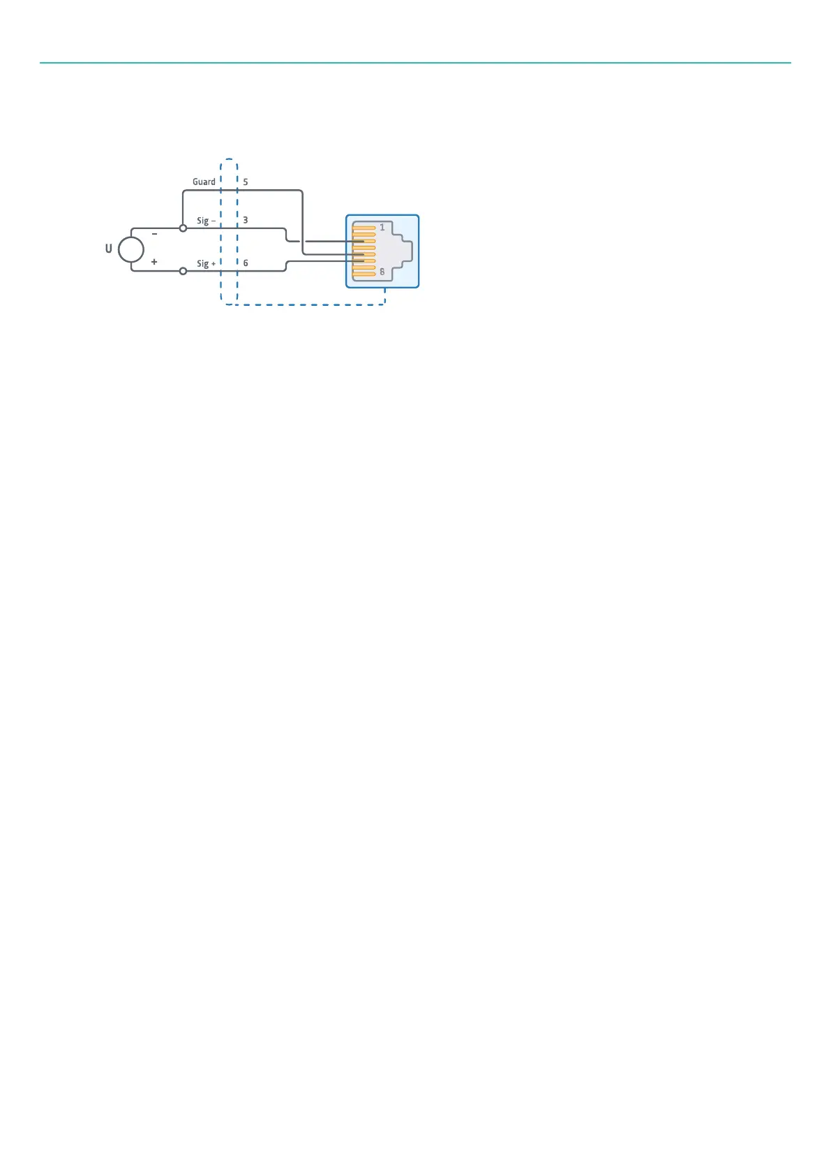
Passive 2-wire configuration with guard:
l
Pin 1: Not connected
l
Pin 2: Not connected
l
Pin 3: Signal –
l
Pin 4: Not connected (TEDS data)
l
Pin 5: Guard
l
Pin 6: Signal +
l
Pin 7: Not connected
l
Pin 8: Not connected
Note that to ensure high common mode rejection, Pin 5 (guard line) needs to be connected to Sig– as close
to the sensor as possible.
Connecting the TEDS chip:
The only way to connect the TEDS chip is between pins 4 and 5.
Quarter-bridge sensors (4-wire/3-wire)
Board type: B201-10
Connector type: 10×RJ45 (each with 8 pins)
Quarter bridges can be connected in a 4-wire or 3-wire configuration. In a 3-wire configuration, there is only
one sense line. Both pin configurations are shown below.
- 28 -