Electrical connections, LEDs
50
a4643-1.0 HBM: public ClipX
(location where the own device is to appear) in your browser (ClipX Bus menu).
Address 1 serves as the bus master; all the other addresses are slaves. Specify
which signal to transmit for each device. The status (valid/invalid) is transmitted
along with the measurement signal. 1000 values per second are transmitted per
device (including CRC check).
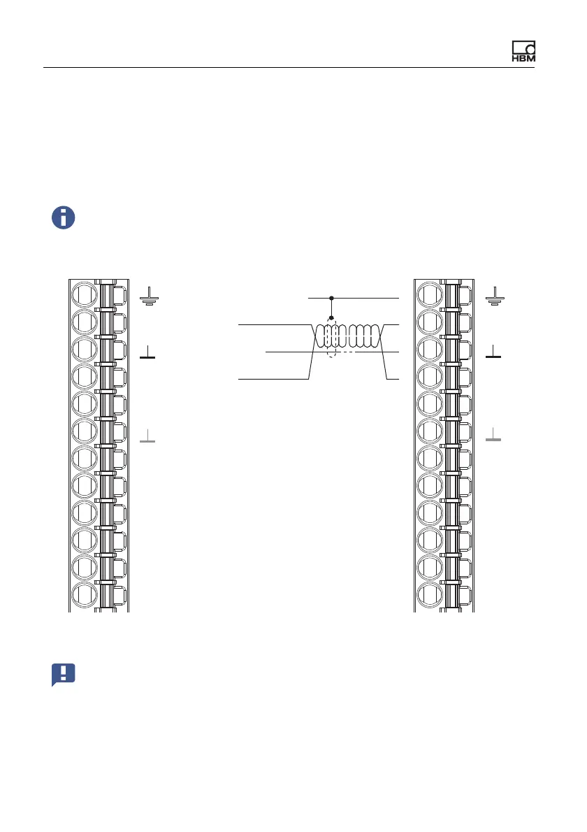
Fig. 26: Plug terminal X2, pin assignment for ClipX bus
If you set Own Address for a device to 0, the ClipX bus will be deac-
tivated for that device, meaning no other devices are visible, and no
own signal can be transmitted.
Important: Termination resistors are not necessary, and must not be
used. The maximum line length between two devices is 30cm.
Housing, cable shields
ClipX bus
ClipX bus GND
ClipX bus
Synchronization
Sync
Sync
Digital In GND
Digital In 2
DI2
DI1
DI
DO2
DO1
Digital In 1
Digital Out 2
Digital Out 1
Supply 0 V
0V
24V
Supply 10 … 30 V
CxA
CxB
CxA
CxB
X
X
DI2
DI1
DI
DO2
DO1
0V
24V
Plug terminal X2, supply, DIO, Sync, ClipX bus