Electrical connections, LEDs
52
a4643-1.0 HBM: public ClipX
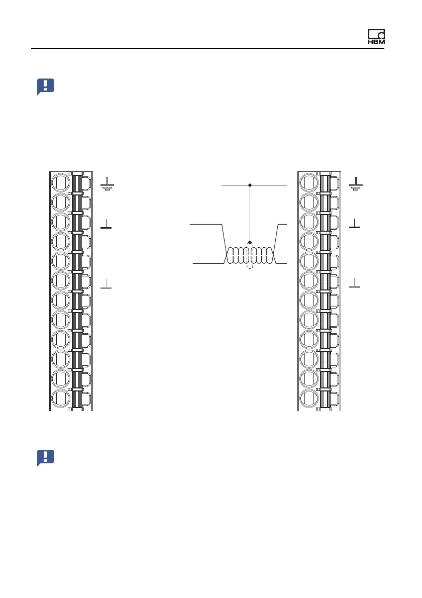
Fig. 28: Plug terminal X2, pin assignment for Sync signal
Important: On the first device you must enable Sync Mode Master
[Master sync mode]. All the others operate as slaves, so the switch
must not be active. Make the setting in your browser using the Am-
plifier and Sensor Type menu items. Synchronization is only possi-
ble for sensor types with carrier frequency (CF), not for DC. No
synchronization of the time base or the A/D converters takes place.
Housing, cable shields
ClipX bus
ClipX bus GND
ClipX bus
Synchronization
Sync
Sync
Digital In GND
Digital In 2
DI2
DI1
DI
DO2
DO1
Digital In 1
Digital Out 2
Digital Out 1
Supply 0 V
0V
24V
Sipply 10 … 30 V
CxA
CxB
CxA
CxB
X
X
DI2
DI1
DI
DO2
DO1
0V
24V
Plug terminal X2, supply, DIO, Sync, ClipX bus
Important: Termination resistors are not necessary, and must not be
used. The maximum line length between two devices is 30cm.