117
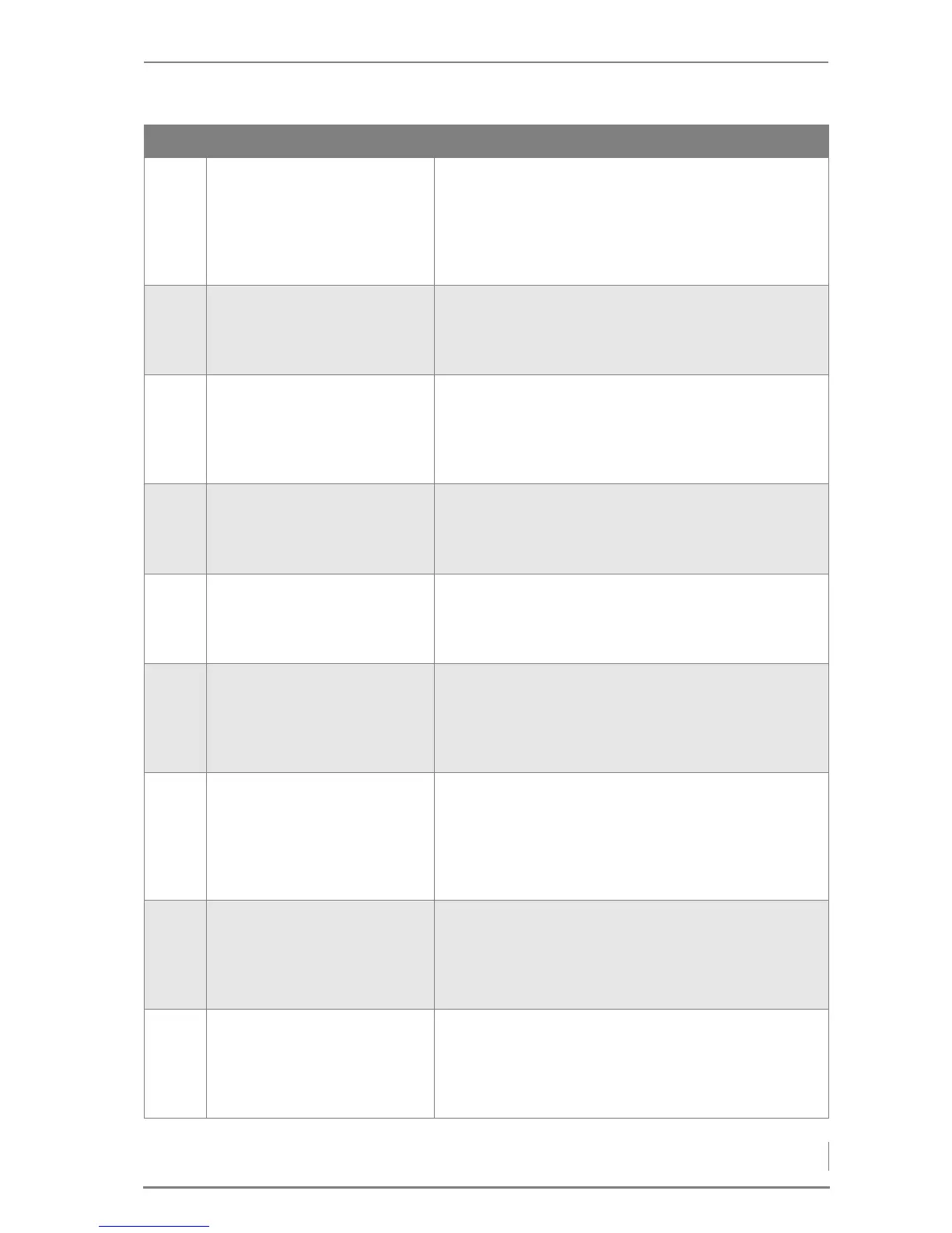
1-10 Serial port
Status display
DAQ boiler+HCR0
DAQ boiler+HCR1
GSM module
Remote maintenance
• Serial interface
For switching functions.
1-11 General information
Mobile phone
number
• Mobile phone number
For entry of the operator's mobile phone number for the
setting GSM module (1-10).
1-17 General information
Correction voltage
Lambda sensor
[mV]
( 0.0) 0.0
• Correction voltage for lambda sensor
Manual readjustment of the lambda sensor voltage.
1-18 General information
Correction voltage
Lambda sensor max [mV]
( 3.0) 3.0
• Maximum correction voltage for lambda sensor
Maximum correction voltage for the lambda sensor at
calibration
1-19 General information
Correction voltage
Lambda sensor min [mV]
( -6.0) -6.0
• Minimum correction voltage for lambda sensor
Minimum correction voltage for the lambda sensor at
calibration
1-20 General information
Comb.chamb.temp. for
calibrating lambda
( 50) 50°
• Combustion chamber temperature for calibrating
lambda
Set the combustion chamber temperature for calibrating
the lambda sensor.
(40 - 800 °C)
1-23 Boiler type
C25
C35
C50
C65
C80
• Boiler type
Selection of the boiler type.
1-24 Language
D - German
GB - English
NL - Dutch
FR - French
• Display language
Setting the language of the display.
1-25 Power supply
3x400V/N
3x230V
1x230V
1x230V R
• Supply voltage
Selection of the supply voltage.
No. Display Description
Table 6/3 - System level / 1 - General