76
See the hydraulic plan and the circuit diagram for the plug connec-
tions and the necessary sensors for your particular hydraulic system.
✎ The available hydraulic solution options can be found in the sec-
tion “4.10 HDG hydraulic systems” in this chapter or in the infor-
mation booklet “Hydraulic Solutions for the HDG Hydronic”.
Take great care that you use the correct sensors (contact sensors, im-
mersion sensors, outside temperature sensors) since, if incorrectly
applied, error messages and resulting malfunctions in the control
system could then occur.
All of the sensors in the HDG Hydronic are PT 1000 sensors.
I
NSTALLING THE OUTSIDE
TEMPERATURE SENSOR
Temperature PT 1000 Temperature PT 1000
-50 °C 803.10 Ohm 25 °C 1097.40 Ohm
-40 °C 842.70 Ohm 30 °C 1116.70 Ohm
-30 °C 882.20 Ohm 40 °C 1155.40 Ohm
-20 °C 921.60 Ohm 50 °C 1194.00 Ohm
-10 °C 960.60 Ohm 60 °C 1232.40 Ohm
0 °C 1000.00 Ohm 70 °C 1270.70 Ohm
10 °C 1039.00 Ohm 100 °C 1385.00 Ohm
20 °C 1077.90 Ohm 150 °C 1573.10 Ohm
Table 4/7 - Characteristics of PT 1000
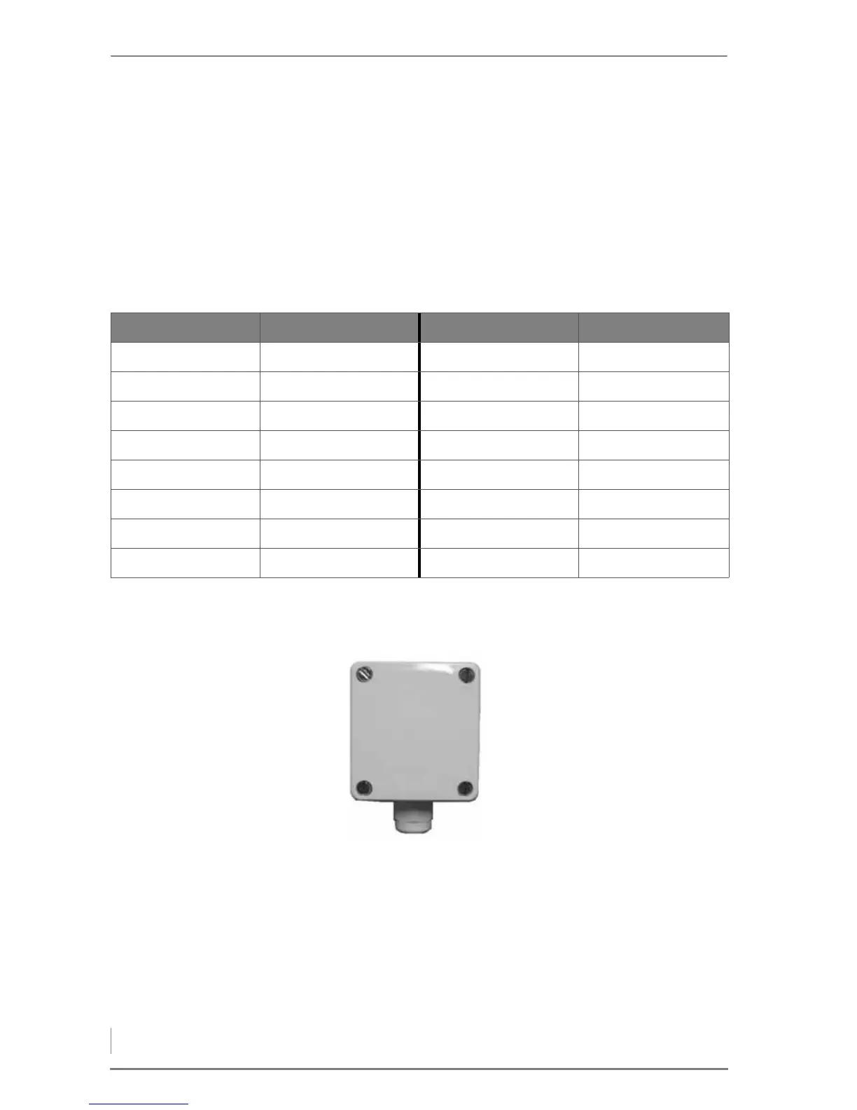
1. Install the outside tempera-
ture sensor at the intended
position on the wall with its
cable outlet pointing down-
wards.
✎ See section “4.2 Connections”
in this chapter.
Figure 4/47 - Outside temperature sensor