92
3. After selecting the respective sensor, press the Plus or Minus
button.
✓ The drives are controlled with the Plus or Minus buttons.
4. For the selected hydraulic system, check the function of the fol-
lowing sensors:
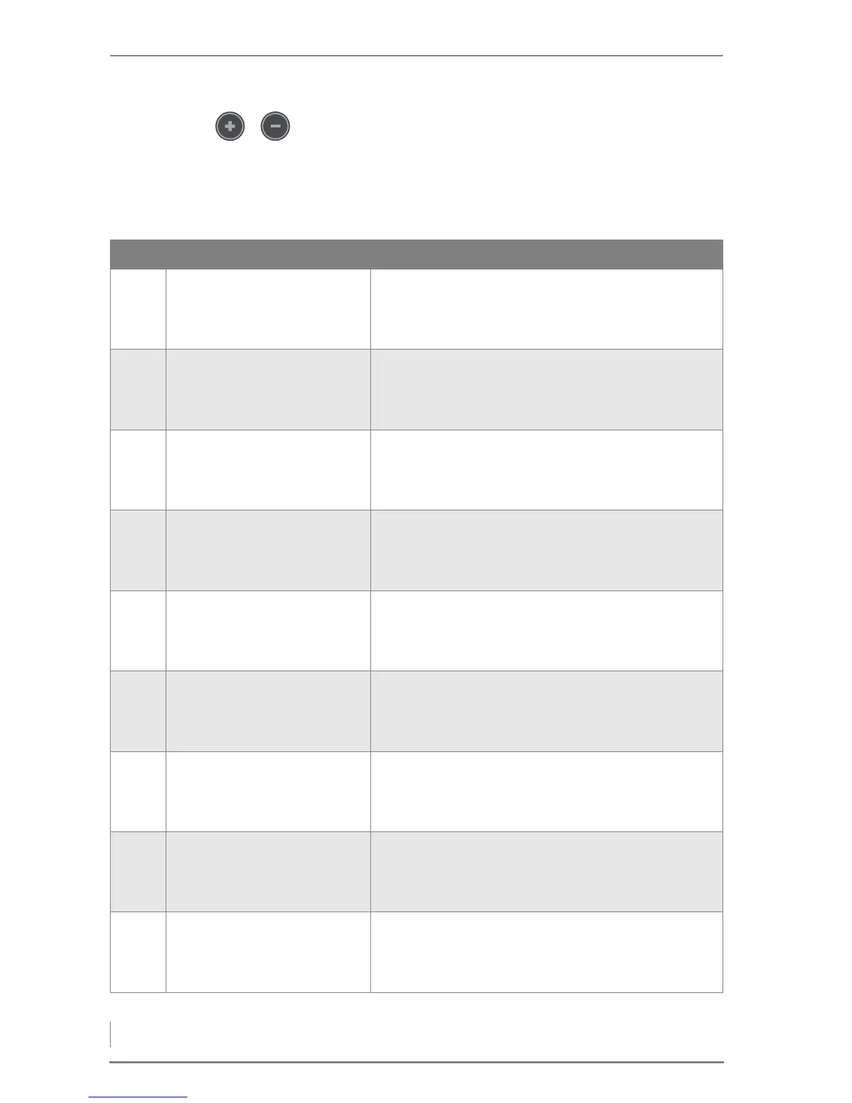
No. Display Description
h-16 Sensor 1
Boiler temp. -1?
Return temp. -1°C
Outside temp. -1°C
Sensor 1
Current boiler temperature
Current return temperature
Current outside temperature
h-17 Sensor 2
Chamber temp. 41°C
Flue gas temp. 41°C
Lambda O2 --.-%
Sensor 2
Current combustion chamber temperature
Current flue gas temperature
Current lambda value
h-18 Sensor 3
Acc. top
Acc. bottom
Sensor 3
Current accumulator temperature at top
Current accumulator temperature at bottom
h-19 Manual HC
Mixing valve HC 1
Open 0 Close 0
(+) (-)
Mixing valve HC 1
Plus button: Mixing valve is opened
Minus button: Mixing valve is closed
h-20 Manual HC
HCP/Thermostat 1
HCP 1: 0 (+)
Room/VL 1: -20/-50°C
Pumps/Indoor thermostat for heating circuit 1
Plus button: Heating circuit pump 1 switches on/off
h-21 Manual HC
Mixing valve HC 2
Open 0 Close 0
(+) (-)
Mixing valve HC 2
Plus button: Mixing valve is opened
Minus button: Mixing valve is closed
h-22 Manual HC
HCP/Thermostat 2
HCP 2: 0 (+)
Room/VL 2: -20/-50°C
Pumps/Indoor thermostat for heating circuit 2
Plus button: Heating circuit pump 2 switches on/off
h-23 Manual HC
Mixing valve HC 3
Open 0 Close 0
(+) (-)
Mixing valve HC 3
Plus button: Mixing valve is opened
Minus button: Mixing valve is closed
h-24 Manual HC
HCP/Thermostat 3
HCP 3: 0 (+)
Room/VL 3: -20/-50°C
Pumps/Indoor thermostat for heating circuit 3
Plus button: Heating circuit pump 3 switches on/off
Table 5/7 - Sensors in manual operation