8.3 Selecting the Connections and Protocol
102
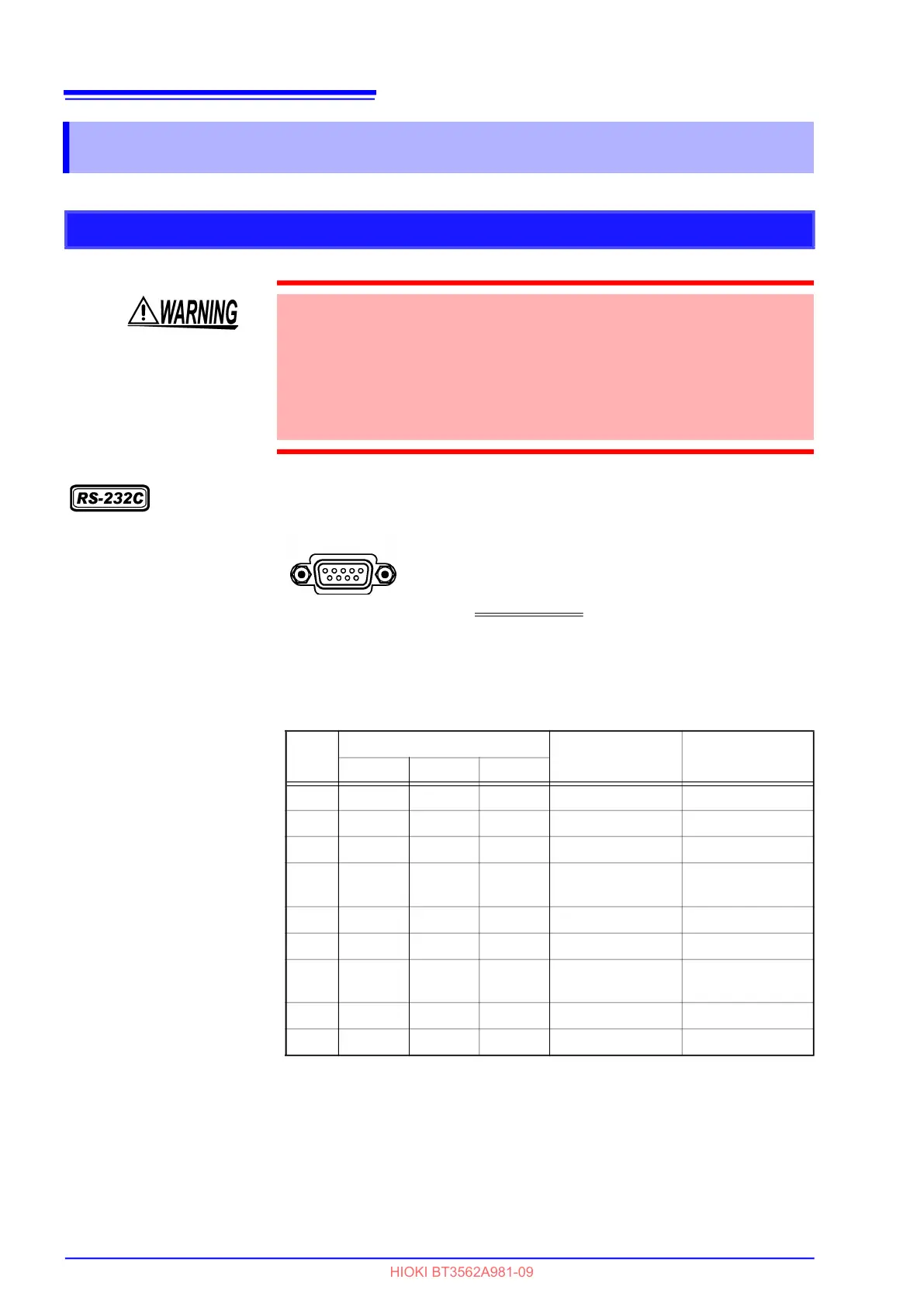
RS-232C Connector
The I/O connector is a DTE (Data Terminal Equipment) configuration.
This instrument uses only pins 2, 3 and 5. The other pins are unconnected.
8.3 Selecting the Connections and Protocol
Attaching the Connector
• Always turn both devices OFF when connecting and disconnecting an inter-
face connector. Otherwise, an electric shock accident may occur.
• After connecting, always tighten the connector screws. The mounting screws
must be firmly tightened or the RS-232C connector may not perform to spec-
ifications, or may even fail.
• To avoid damage to the instrument, do not short-circuit the connector and do
not input voltage to the connector.
Male 9-pin D-sub
#4-40 attaching screws
Connect the RS-232C cable.
To connect the instrument to a controller (DTE),
use a crossover cable
compatible with the connec-
tors on both the instrument and the controller.
6 7 8 9
1 2 3 4 5
Pin
No.
Signal Name
Signal Notes
Common EIA JIS
1 DCD CF CD Unused No connection
2 RxD BB RD Receive Data
3 TxD BA SD Transmit Data
4
DTR CD ER
Data Terminal
Ready
Internally connected
to +5 V
5 GND AB SG Signal Ground
6 DSR CC DR Unused No connection
7
RTS CA RS
Request to Send Internally connected
to +5 V
8 CTS CB CS Unused No connection
9 RI CE CI Unused No connection
 Loading...


