3.6 Zero-Adjust Function
35
3
Chapter 3 Measurement
Execute zero adjustment before measuring to nullify any residual offset voltage
from the instrument or measurement environment. Measurement accuracy spec-
ifications are applicable after zero adjustment. Zero adjustment can also be exe-
cuted by the 0ADJ terminal of the EXT I/O connector.
See "5.2 Signal Descriptions" (p.80).
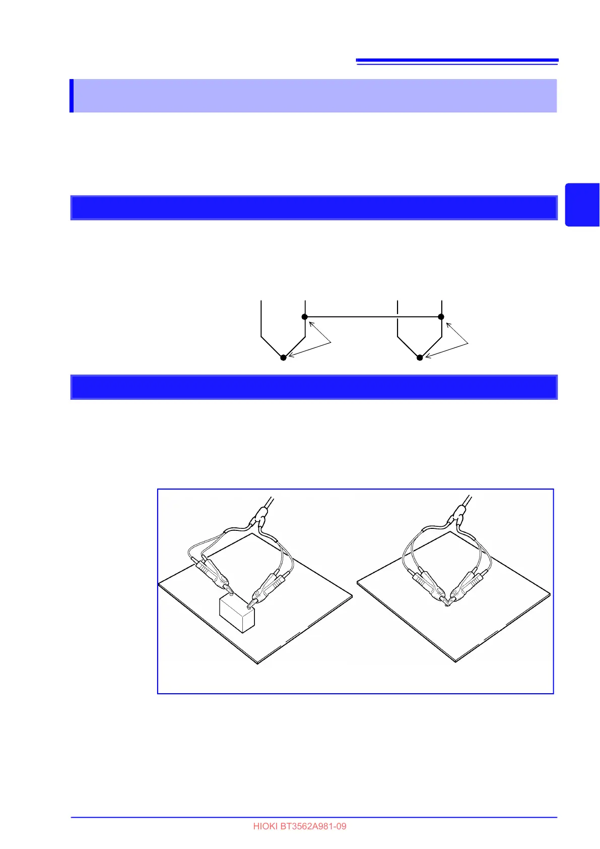
Before executing zero adjustment, connect the test leads (probes) as follows:
1. Connect SENSE-H to SENSE-L.
2. Connect SOURCE-H to SOURCE-L.
3. Connect the joined SENSE and SOURCE leads together as shown below.
3.6 Zero-Adjust Function
Wiring Method for Zero-Adjustment
Connection
Connection
SENSE-H SENSE-L
SOURCE-H SOURCE-L
Executing Zero-Adjustment
1
Position the measurement leads in the actual measurement state.
Since the amount of zero adjustment varies with the position and state of the mea-
surement leads (probes) (i.e., their length, shape, position, etc.), the measure-
ment leads must be positioned in the actual measurement state before performing
zero adjustment.
These variations are particularly pronounced in the 3 m and 30 m ranges, so
be sure to position the leads in same state as will be used to perform actual mea-
surement when using those configurations.
at zero adjustment at measurement