2.3 Connecting the Optional Test Leads
21
2
Chapter 2 Measurement Preparations
Test leads are not included as standard accessories with the instrument, so the
appropriate options need to be purchased separately or constructed according to
the user’s application requirements. To construct custom test leads, refer to "Pre-
cautions for Making Custom Test Leads"(p.A1). The resistance measurement ter-
minals on this instrument consist of four separate banana jacks.
See "Appendix 1 Precautions for Making Custom Test Leads"(p.A1).
About Test Leads ______________________________________________
(Example: Model L2107 CLIP TYPE LEAD)
2.3 Connecting the Optional Test Leads
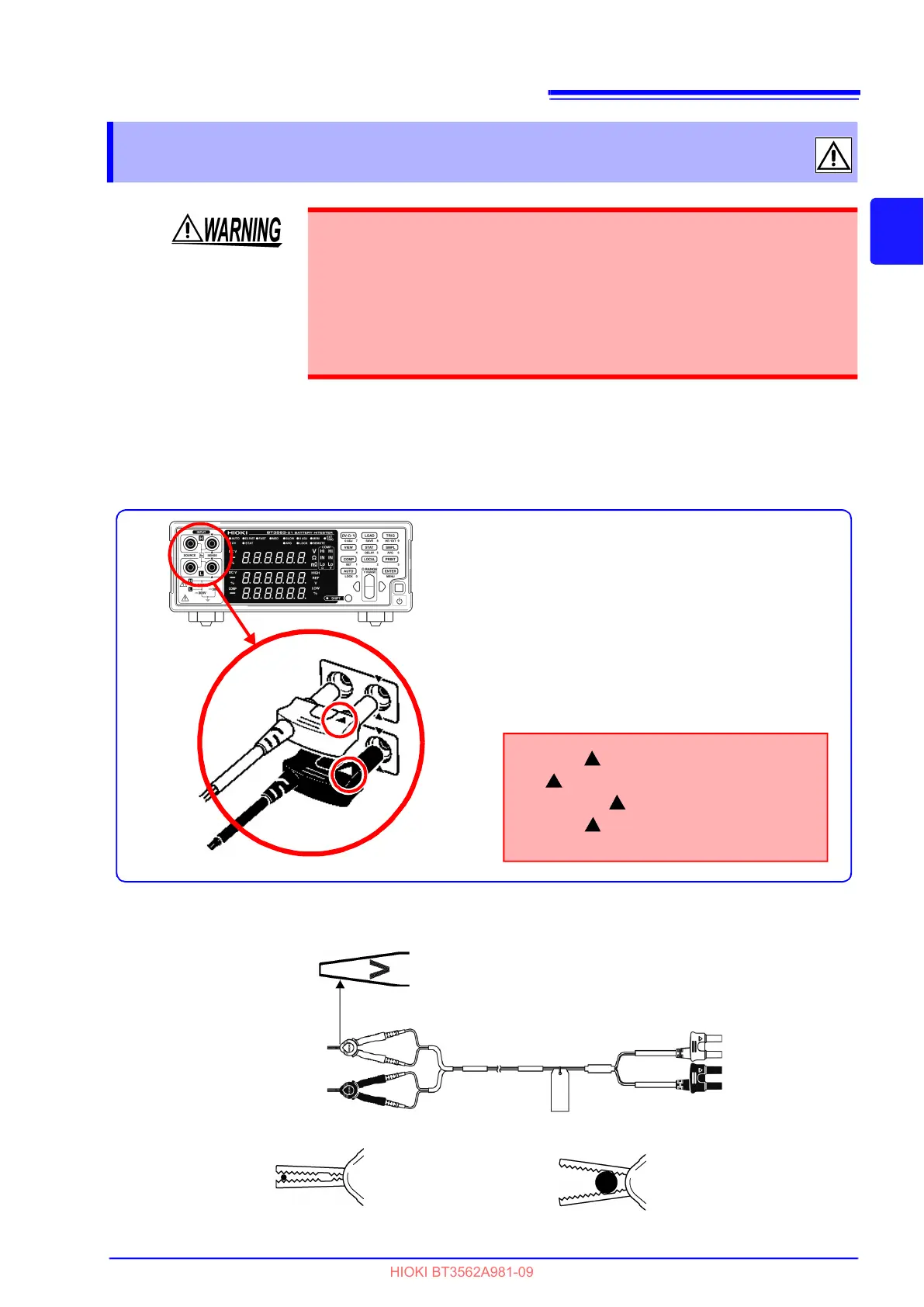
• To prevent an accident caused by short-circuiting the battery, be sure to verify
that nothing is connected to the tips of the measurement leads before connect-
ing the leads to or disconnecting them from the instrument. (Contact between
the banana terminals while the tips of the measurement leads are connected
to the battery will short-circuit the battery, possibly resulting in serious injury.)
• To prevent electrical shock, verify the ratings of the measurement leads before
measurement and exercise care not to measure voltages that exceed those
ratings.
Plug the mark on the red lead into the
red marked jack on the instrument,
and plug the mark on the black lead into
the black marked jack on the instrument.
Example: Optional model L2107 CLIP TYPE LEAD
Black Lead
Red Lead
1. Confirm that the instrument's Power
switch is OFF.
2. Verify that nothing is connected to the tips
of the four-terminal measurement leads.
3. Connect four-terminal test leads such as
the L2107 CLIP TYPE LEAD to INPUT.
SOURCE
SENSE
SENSE
SENSE
SOURCE
SOURCE
SOURCE
SENSE
Red
Black
Red
Black
The side with “V” mark is SENSE.
When clipping a thin line
(Clip the line at the tip,
serrated part of the
jaws.)
When clipping a thick line
(Clip the line at the
deep, non-serrated part
of the jaws.)