4.1 Comparator Function
47
4
Chapter 4 Applied Measurement
This example describes the comparator setting method.
• The upper and lower thresholds are saved as the displayed counts (indepen-
dent of measurement mode and range). Therefore, changing the measure-
ment mode or range results in the same display counts representing different
absolute values.
Example:
To specify the lower threshold as 150 m
in the 300 m range, enter “15000”.
Switching to the 3
range after making this setting changes the lower thresh-
old to 1.5 .
• The instrument can also base judgments on the absolute value of voltage
measured values (to prevent Lo judgments when the positive and negative
terminals are connected backwards).
See "Configuring the Absolute Value Judgment Function (Voltage)" (p.55)
Comparator Setting Example 2 (Reference Value and Tolerance Judgment)
Example:
Set a reference value and tolerance in the V mode (3 range), and set the beeper
to sound while measured values are within tolerance.
Resistance : Reference value 1.5 , Tolerance 5%
Voltage : Reference value 4.2 V, Tolerance 0.5%
1
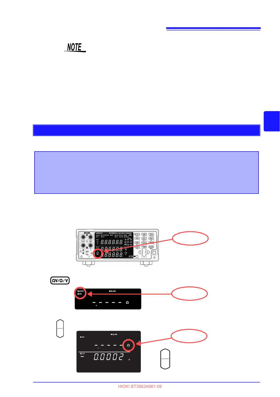
Confirm that the Comparator function is OFF.
First make sure the Comparator function is disabled. Settings cannot be changed while
the Comparator function is enabled. Press the COMP key, if necessary, to disable the
Comparator function.
2
Select the V measurement mode.
3
Select the measurement range (for this example, the 3 range).
COMP not lit
V lit
Increase the resistance measurement range.
Decrease the resistance measurement range.
lit