5.3 Timing Chart
85
5
Chapter 5 External Control (EXT I/O)
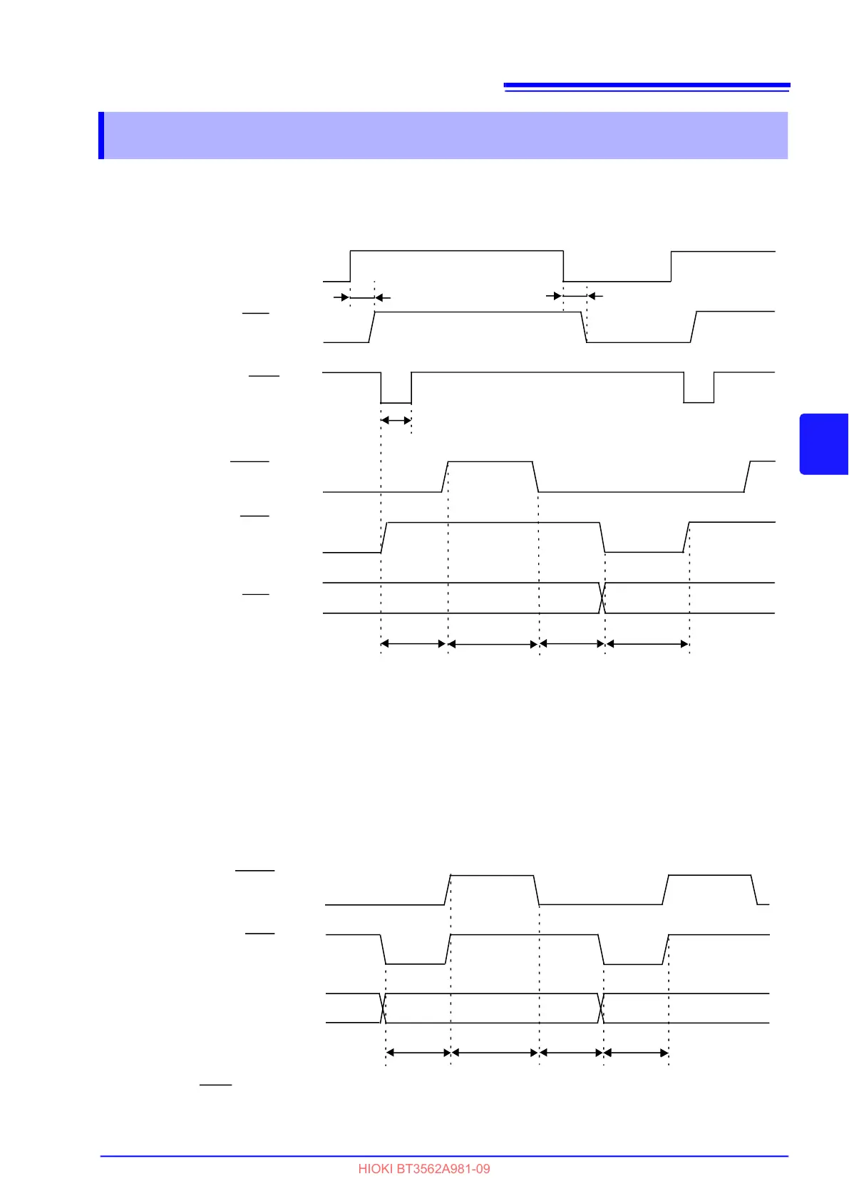
External Trigger Timing Chart
Internal Trigger Timing Chart
5.3 Timing Chart
Contact State
*1 ERR
Output
(Err Output ASYNC Setting)
*3 TRIG
Input
Measurement start signal
INDEX
Output
Reference Signal
EOM
Output
End-of-Measurement Signal
Comparator Result
*2 ERR
Output
(Err Output SYNC Setting)
Contact
Open
End of Conversion
Measuring
*1: For details, see “"ERR Output" (p.83).”
*2: When ERR output is set to the SynChronous mode, measurement fault detection results can be obtained
when measurement is finished, as with comparator results.
*3: After connecting to the test object, wait for longer than the response time (approximately 10 ms) before
inputting the TRIG signal (It is necessary to wait out the response time for the measurement values to sta-
bilize after connection. Response times depend on the test object).
t1 t1
t2
t3
t4 t5 t6
ON OFF
ON
OFF
OFF
ON
OFF
ON
Measuring Measuring
t3
t4 t5
* INDEX Output
Reference Signal
* EOM
Output
End-of-Measurement
Signal
Comparator Result
* When the EOM signal is set to PULSE, the signal will remain on only for the specified period upon com-
pletion of conversion.
t6
OFF
ON
ON
OFF