Appendix 7 Calibration Procedure
A9
Appendix
For the calibration environment, see Section "Chapter 9 Specifications" (p.181).
Calibration of the
Ohmmeter
• Use the 9453 FOUR TERMINAL LEAD as the connection lead.
• Use standard resistors with excellent temperature characteristics that resist
deterioration over time.
• To prevent influence by the lead, use four-terminal resistors (Non-inductive
type).
• Use a resistor that will reflect the correct resistance at 1 kHz. With wire-wound
resistors, the inductance element is so large that the pure resistance (DC
resistance) does not equal the effective resistance (real part of impedance,
displayed on the instrument).
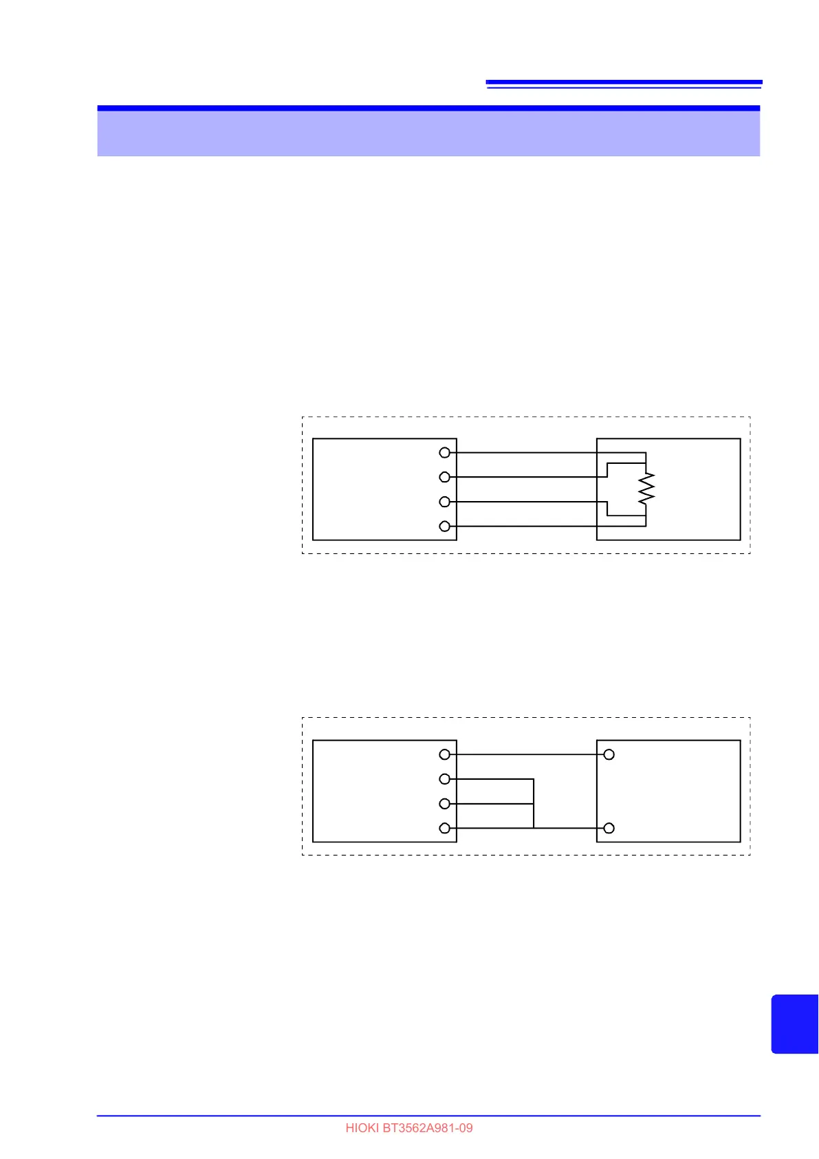
• For connection of a standard resistor to the instrument, see the figure below.
Calibration of the
Voltmeter
• Use a generator that can output a DC voltage of 300 V DC.
• For connection of a generator to the instrument, see the figure below.
• Do not apply an alternating current from the instrument to the generator, as
the generator may malfunction.
• Use a low-impedance voltage source.
• The instrument may not operate properly with some generators.
Appendix 7 Calibration Procedure
Model BT3562 ,BT3563
SENSE - Hi
SENSE - Lo
SOURCE - Hi
SOURCE - Lo
Standard
Resistor
SENSE - Hi
SOURCE - Hi
SENSE - Lo
SOURCE - Lo
+
-
DC Generator
Model BT3562,BT3563
 Loading...


