Appendix 10 Rack Mounting
A17
Appendix
By removing the screws on the sides, this instrument can be installed in a rack mounting plate.
Rack Mounting Plate Template Diagram and Installation Procedure _________
Appendix 10 Rack Mounting
Observe the following precautions regarding the mounting screws to
avoid instrument damage and electric shock accidents.
• When installing the Rack Mounting Plate, the screws must not intrude
more than 6 mm into either side of the instrument.
• When removing the Rack Mounting Plate to return the instrument to
stand-alone use, replace the same screws that were installed origi-
nally. (Feet: M3 x 6 mm, Sides: M4 x 6 mm)
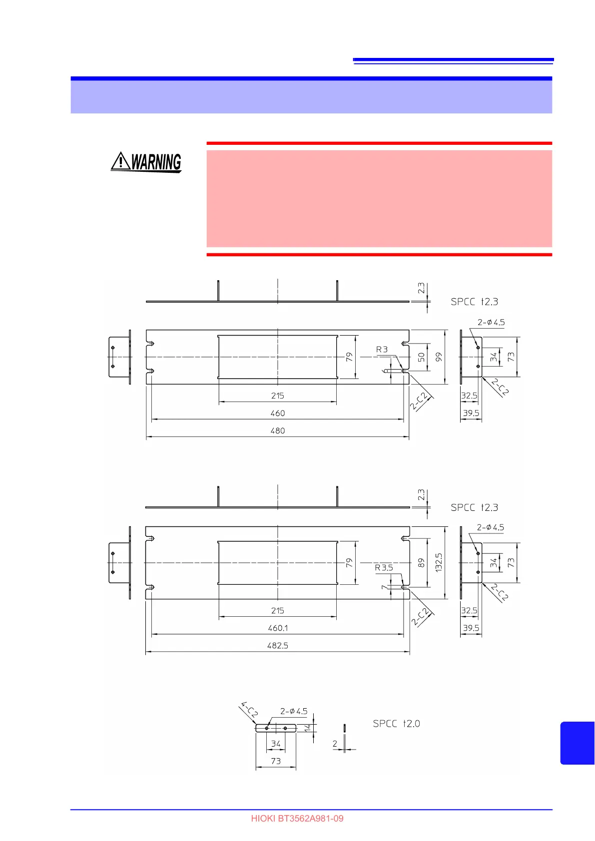
Rack Mounting Plate (JIS)
Rack Mounting Plate (EIA)
Spacer (Two Required)