5.2 Signal Descriptions
80
Pos: positive, Neg: negative,: not applicable
5.2 Signal Descriptions
Pinout
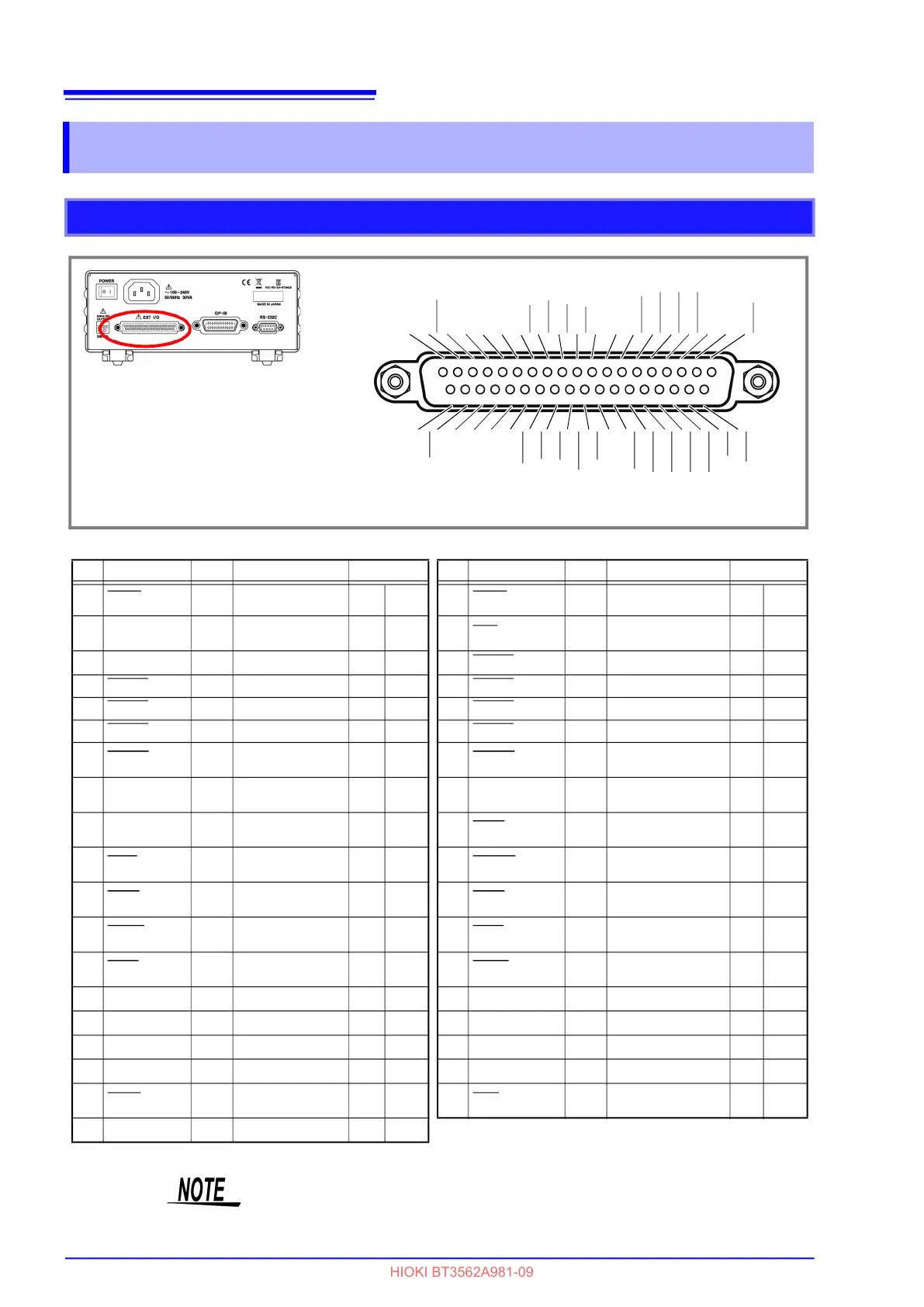
EXT I/O Connector (Instrument Side)
Connector: (Instrument Side)
37-pin D-sub female with #4-40 screws
Mating Connectors:
DC-37P-ULR (solder type) /
DCSP-JB37PR (pressure weld type)
Japan Aviation Electronics Industry Ltd.
TRIG
(Reserved)
(Reserved)
LOAD1
LOAD3
LOAD5
MANU
ISO_5V
ISO_COM
ERR
R_HI
R_LO
V_IN
(Reserved)
(Reserved)
(Reserved)
(Reserved)
PASS
(Reserved)
0ADJ
CAL
LOAD0
LOAD2
LOAD4
LOAD6
PRINT
ISO_COM
EOM
INDEX
R_IN
V_HI
V_LO
(Reserved)
(Reserved)
(Reserved)
(Reserved)
FAIL
12345678910111213141516171819
202122232425262728293031323334353637
Pin
Signal name I/O Function Logic Pin Signal name I/O Function Logic
1 TRIG
IN
External trigger
Pos/
Neg
Edge
20 0ADJ
IN
Zero adjustments Neg
Edge
2
(Reserved)
21
CAL
IN
Self-calibration
execution
Neg
Edge
3
(Reserved)
22
LOAD0
IN
Load no. bit 0 Neg Level
4
LOAD1
IN
Load no. bit 1 Neg Level
23
LOAD2
IN
Load no. bit 2 Neg Level
5
LOAD3
IN
Load no. bit 3 Neg Level
24
LOAD4
IN
Load no. bit 4 Neg Level
6
LOAD5
IN
Load no. bit 5 Neg Level
25
LOAD6
IN
Load no. bit 6 Neg Level
7
MANU
IN
Comparator manu-
al control
Neg Level
26
PRINT
IN
Print measured val-
ue
Neg Edge
8
ISO_5V
Isolated 5 V power
output
27
ISO_COM
-
Isolated common
signal ground
9
ISO_COM
Isolated common
signal ground
28
EOM
OUT
End of measurement Neg Edge
10
ERR
OUT
Measurement fault Neg Level
29
INDEX
OUT
Analog measure-
ment finished
Neg Edge
11
R_HI
OUT
HI resistance
judgment result
Neg Level
30
R_IN
OUT
IN resistance
judgment result
Neg Level
12
R_LO
OUT
LO resistance judg-
ment result
Neg Level
31
V_HI
OUT
Hi voltage judgment
result
Neg Level
13
V_IN
OUT
IN voltage judg-
ment result
Neg Level
32
V_LO
OUT
Lo voltage judgment
result
Neg Level
14
(Reserved)
OUT
33
(Reserved)
15
(Reserved)
OUT
34
(Reserved)
16
(Reserved)
OUT
35
(Reserved)
17
(Reserved)
OUT
36
(Reserved)
18
PASS
OUT
PASS judgment re-
sult
Neg Level
37
FAIL
OUT
Judgment result
FAIL
Neg
Level
19
(Reserved)
OUT
Reserved pins are not connected inside the instrument.
Do not connect to reserved pins.
The connector frame is connected to (continuous with) both the instrument's
case (the metal cabinet surrounding the instrument) and the power inlet's protec-
tive ground pin. Note that the frame is not isolated from the ground.