OPERATOR'S STATION
1-45
ADJUSTING THE SEAT
Seat Height and Angle Adjustment
Seat height adjustment range is 60 mm (2.4 in) with
steps every 15 mm (0.6 in) (5 positions in total). More-
over, the height of the front part and the rear part of the
seat are adjusted independently, thus allowing the angle
of the seat to be adjusted.
CAUTION: Avoid possible injury while operating
lever (1). When pushing down lever (1), do not
grab it. Fingers may be pinched between lever (1)
and the seat stand. Be sure to push on the upper
face of lever (1).
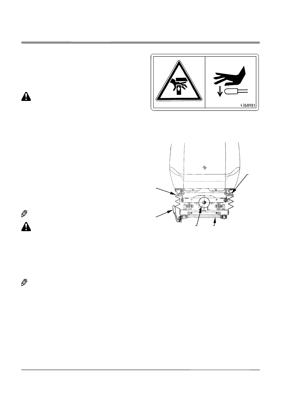
Use lever (1) to adjust the seat height and/or seat angle
as follows:
•
To adjust the front part of the seat:
Push down lever (1) while sitting on the seat, and ap-
ply or remove body weight to obtain the desired height.
When the desired height is obtained, release lever (1).
•
To adjust the rear part of the seat:
Pull up lever (1) while sitting on the seat, and apply or
remove body weight to obtain the desired height.
When the desired height is obtained, release lever (1).
Console and Seat Fore-aft Adjustment
Pull lever (2) to the right to adjust the seat and both right
and left consoles to desired distance from the travel
pedals and levers. Release lever to lock seat and con-
soles into position.
NOTE: Seat and console fore-aft adjustment range is
60 mm (2.4 in) with steps every 20 mm (0.8 in).
CAUTION: In case the control levers are pulled
fully backward with the seat in the forward most
position, the control levers may come in contact
with the arm rest. Always check that the levers
can be fully stroked before starting operation.
Seat Fore-Aft Adjustment
Pull lever (3) to the right to unlock the seat from both
consoles. With lever held to the right, slide the seat to
the desired distance from pilot control levers. Release
the lever.
NOTE: Seat fore-aft adjustment range is 160 mm (6.3
in) with steps every 16 mm (0.8 in).
Suspension Adjustment
Turn knob (4) clockwise to increase suspension stiff-
ness.
Turn knob counterclockwise to decrease suspension
stiffness.
Backrest Adjustment
Pull up lever (5) to release backrest lock. Move backrest
to the desired position and release the lever.
SS-747
M1GF-01-006
Push down with
the palm.
Caution: Possibility
of pinched fingers
5
2
3
4
1