44 MDR 710 – WWL Conveyor | Maintenance Manual | 29349817
November 16, 2020
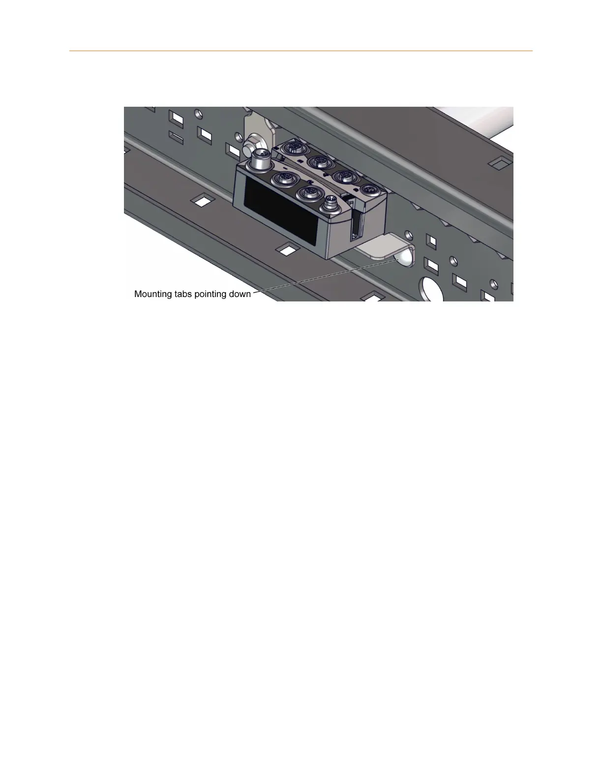
Figure 4-2 Remote I/O Installed in a Curved Section
Ensure that the module is centered between protruding roller axles so that there is
no interference with cable connections and routing. Ensure that the remote I/O
module does not contact or interfere with any other components in the assembly.
If there is component or cable routing interference, such as the protruding roller axles
making contact with the remote I/O module, connectors, or cables, adjust the module
in the side frame mounting slots until the interference is eliminated.
4.7 Photo-Eye Inspection and Replacement
4.7.1 Inspecting a Retro-Reflective Photo-Eye
Retro-reflective photo-eyes transmit and receive light reflected off a reflector
mounted on the opposite rail. This type of photo-eye has two status LEDs, a green
LED for power, and an amber LED for alignment. The power LED should be lit
whenever the photo-eye is receiving power. The alignment LED should be lit when
the sensor is receiving transmitted light reflected off the reflector.
If the power LED is not lit, check that the control card is receiving power. If the
control card is receiving power, check the wires to the photo-eye for damage or loose
connections. If this does not fix the problem, replace the photo-eye.
If the alignment LED is not lit when nothing is blocking the sensor, or if it is flashing,
check the reflector for alignment or damage and adjust if necessary. If this does not
fix the problem, replace the photo-eye.