4188-856_issue 7_07/15_Generic Vigilon (Compact + VA) Comms. 19
Vigilon 4/6 loops & Compact (VA) panels & network nodes
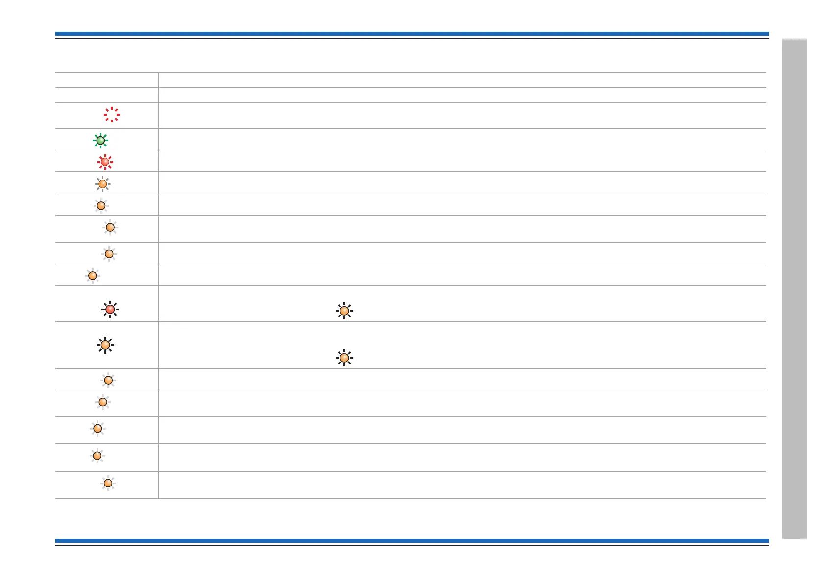
Controls and indications
Indications applicable for all Vigilon panels
Indicators Description
Display The Display provides messages of the system status / events by means of 8 lines by 40 characters per line display.
(red)
Hidden-until-lit fire zones indicators. When "Zones" text and number(s) are illuminated it indicates that a FIRE has been detected in the
specific zone(s). (Zone indicators are not applicable for BS Vigilon panels and Network Nodes)
(green)
When illuminated it indicates that a supply to the panel is present.
(red)
When illuminated it indicates that a FIRE has been detected in the protected premises.
(amber)
When illuminated it indicates that the Verify button has been pressed and the alarm sounders in the system are delayed from sounding.
(amber)
When illuminated it indicates that a FAULT has been detected in the fire detection and alarm system or in the audio system.
(amber)
When illuminated it indicates that a fault has occurred with the system processor. It is important to investigate this fault because the
fire alarm system may not be able to detect fires.
(amber)
Applicable for EN Vigilon panels only. When illuminated it indicates that a part of the system has been disabled.
(amber)
Applicable for BS Vigilon panels only. When illuminated it indicates part of the system has been disabled, delayed or not functioning.
Fire routing O/P
Active
(red)
Applicable for EN panels only from mid 2015 onwards. When illuminated it indicates the Fire Alarm Routing Equipment is active.
Prior to mid 2015 this LED was
CB253 (amber) and it operates with Command Build 253.
Fire routing O/P
Fault/Dis
(amber)
Applicable for EN panels only from mid 2015 onwards. When illuminated and steady it indicates the Fire Alarm Routing Equipment is
faulty. When illuminated and flashing it indicates the Fire Alarm Routing Equipment is disabled.
Prior to mid 2015 this LED was
CB254 (amber) and it operates with Command Build 254.
(amber)
When illuminated it indicates the battery or mains supply to the panel has failed.
(amber)
Applicable for EN Vigilon panels only. When illuminated (always with either the FAULT light or the DISABLEMENT light) it indicates that
there is a sounder fault (flashing indication) or sounder disablement (steady indication).
(amber)
Applicable for EN Vigilon panels only
When illuminated it indicates that one or more delay blocks are setup on the panel.
(amber)
Applicable for EN Vigilon panels only
When illuminated it indicates one or more zones are in Test mode.
(amber)
Applicable for BS Vigilon panels only
When illuminated it indicates panel is in commissioning mode.
 Loading...