Figure 17. General Status Over Range detail
Negativevaluesarenotdisplayedanddonotappearonthe
4-20mAoutput,buttheyareindicatedbyfaultsorwarnings
whenpresetthresholdsareexceeded�(Seezerodeviationin
Section6�1�1)
Inadditiontothegraphicalarm,fault,andwarningindicators,
theLEDsonthefrontpanelashinthesepatternsbasedonthe
condition:
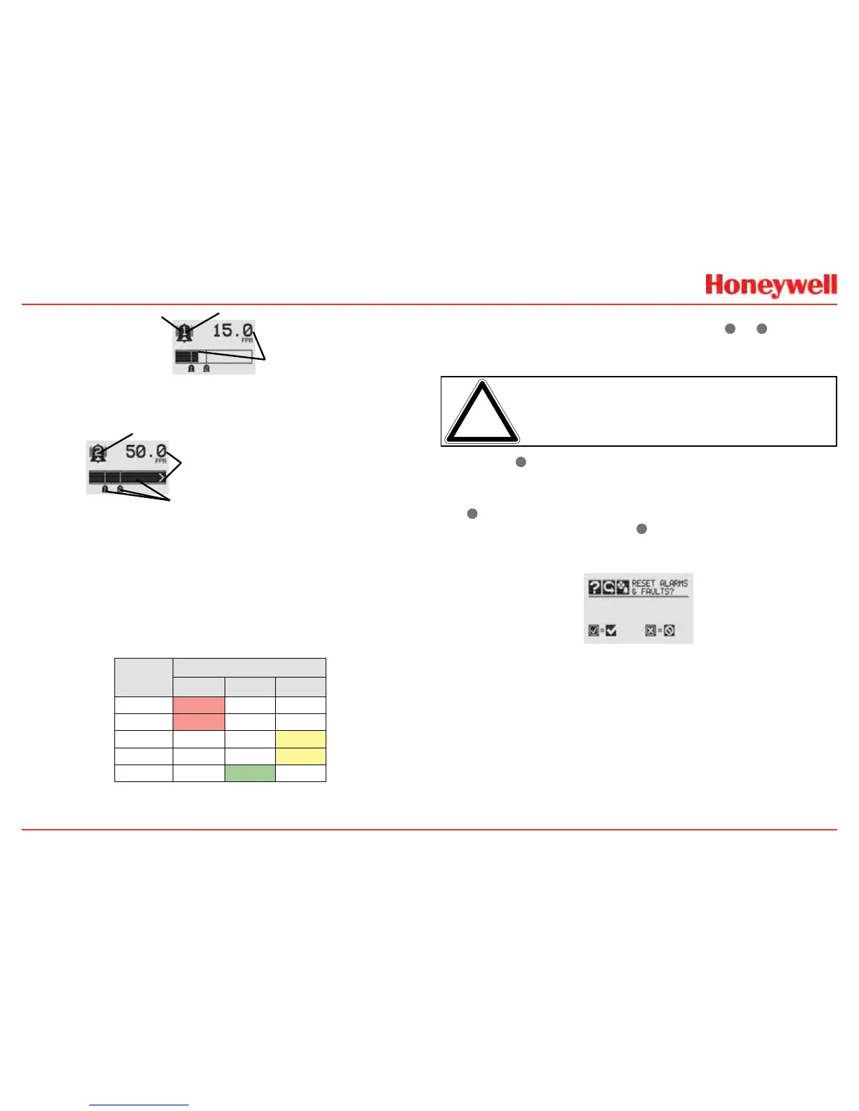
Condition
LED
1
Red Green Yellow
Alarm1 Solid
Alarm2 Flashing
Warning Solid
Fault Flashing
2
Health Flashing
1
TherefreshrateoftheLEDsis0.5second.
2
Specialstates(Warmup,Inhibit)arenotindicatedbytheFaultLED.
1.4.3 Entering the Menu Structure
Swipingthemagnetoverthemagneticswitch
✓
or
✖
allowsthe
usertoresetfaultsoralarms,displaycurrentsettings,ormake
adjustmentstothedevice�
Note: IftheEasyResetoptionissettoLock,alarmsandfaults
cannotberesetwithoutlogginginorenteringapasscode.Formore
information,seeSection2.5.1ConfigureSecurity.
Swipingthe
✖
or“escape”magneticswitchactivatestheAlarm
Re-setscreenandallowsalarmstobesilencedandfaultstobe
reset�
The
✓
switchresetsallalarmsandfaultsandreturnstothe
GeneralStatusScreen�Usethe
✖
switchtoreturntothe
GeneralStatusScreenwithoutresettingthealarmsandfaults�
Figure 18. Alarm Reset screen
Twoauthorizationlevelscontrolaccessbaseduponthesecurity
leveloftheuser:Level1(routinemaintenance)andLevel2
(technicianandpasswordadministrator)�Thedefaultpasscodes
forbothlevelsare“0000”andmustberesetafterinstallation
tocontrolaccess(seeSection2�5�1ConfigureSecurity)�In
general,accesstoneithersecuritylevelrestrictstheuserto
viewingthetransmitter’sdisplay�Ifdesired,theEasyResetfrom
MainStatusoption
allowsalarmandfaultresetswithoutrequiring
accesstoeithersecuritylevel�
 Loading...


