48
Note:
HoneywellAanalyticsrecommendsthatExcelorOptimaandtheXNXtransmitterbewiredtobuilding
ground.Thesystemshouldbegroundedatonlyonepoint.
HART
20 mA
Operation
LOCAL
J1
S1
+V 1-1
Searchline
Searchpoint
4-20mA
HART
18-32 VDC
13.2W max.
1-2
-V 1-3
1-4
+mA 1-5
-mA 1-6
1-7
- Ir
+ Ir
1-8
Sig 1-9
S1
Source
Sink
Isolated
S2
S2
Ir TB-1
TB-2 Ir Data
S3
Source
Sink
S4
▼▼
▲▼
▼▲
S2S1
Isolated
Sink
Source
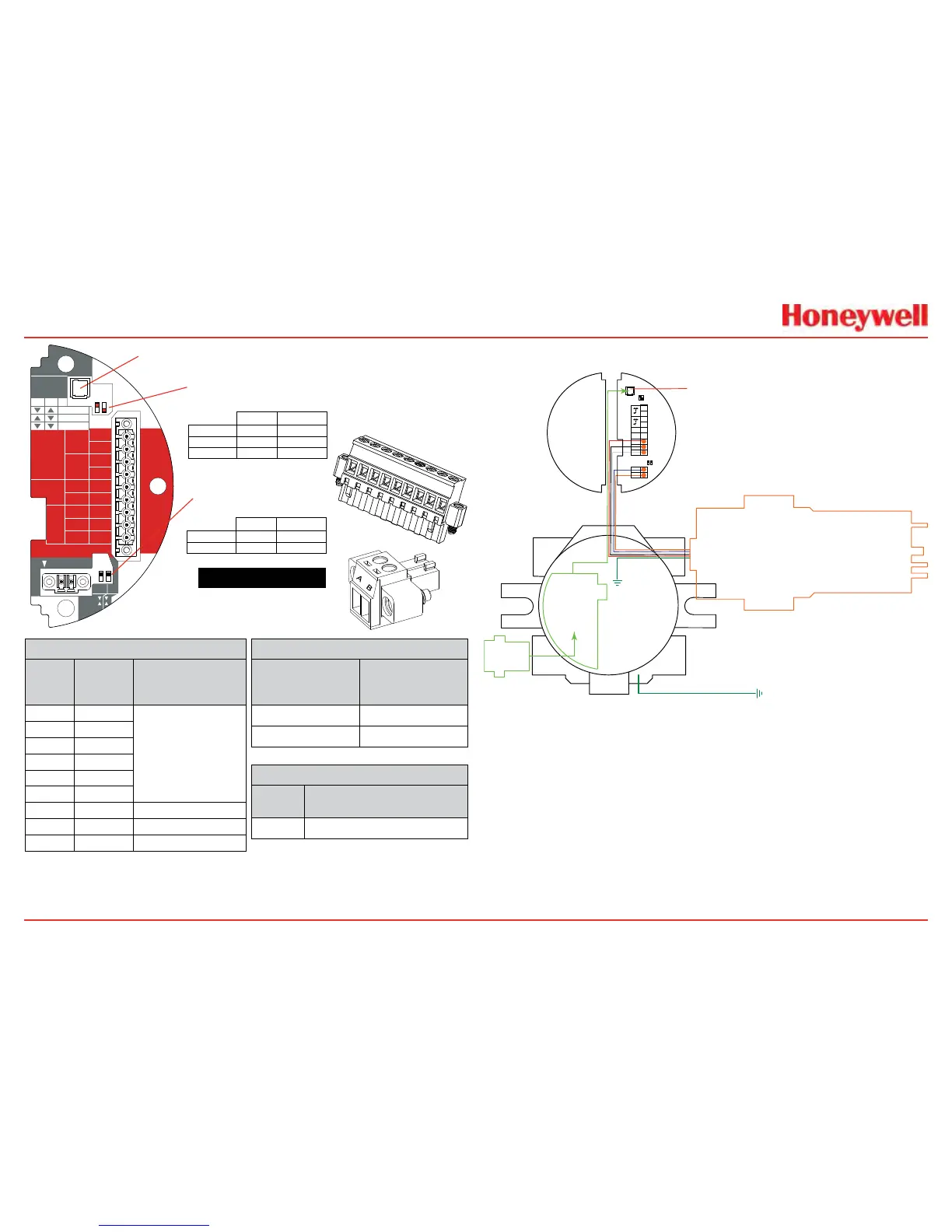
J1 - Local HART Connector
S1 and S2 - 20mA Output
Jumper Switch
S3 and S4 - IR 20mA Input
Jumper Switch
XNX IR TB-1
▼
▲
▼
▲
S4S3
Sink
Source
TB2
Terminal No.
From Searchpoint
Optima Plus
Searchline Excel
A Blue
B Orange
TB1
Terminal
No.
Desc.
From Searchpoint
Optima Plus
Searchline Excel
1 +24v
SeeSection2.2.4
CommonConnections
.
2
3 0VDC
4
5 +20mA
6 -20mA
7 +24VDC Red
8 0VDC Black
9 Sig-20mA White
XNX
Desc.
From Searchpoint Optima Plus
Searchline Excel
Earth Green/Yellow
1
2
3
4
5
6
7
8
9
TB1
TB2
Figure 51. XNX IR
Personality Board Terminal
Blocks, Jumper Switches
and Wiring Guide
Local HART
IS Barrier
(optional)
HART
Adaptor
Optional Local HART
IS Barrier must be
connected to J1
Searchpoint
Optima Plus
4
3
2
1
Sig
Gnd
+24
+
9
8
7
6
5
J1 HART
S1 S2
Terminal Block 1
B
A
2
1
Terminal Block 2
IR Data
S3 S4
To Building
 Loading...


