49
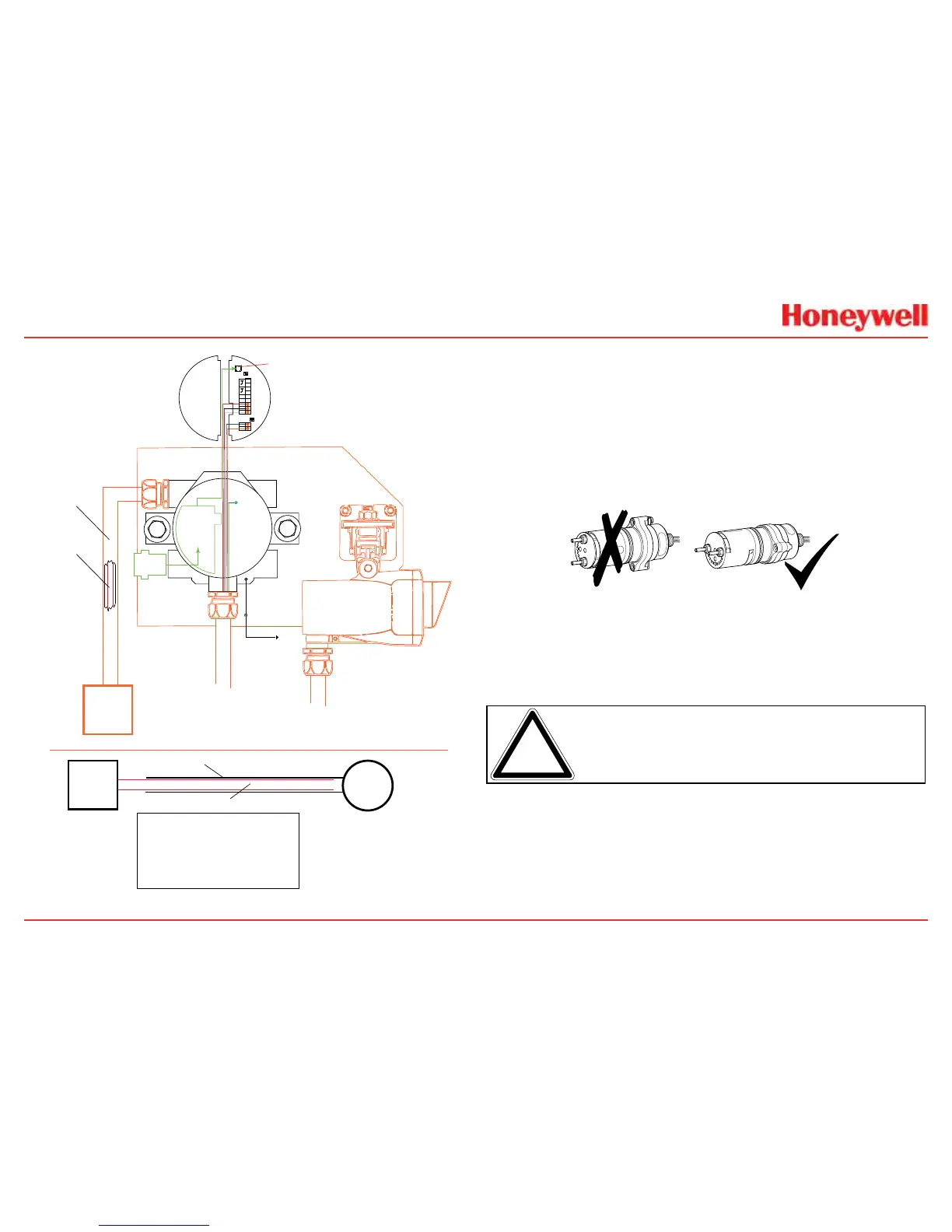
Local HART
IS Barrier
(optional)
Optional Local HART
IS Barrier must be
connected to J1
4
3
2
1
Sig
Gnd
+24
+
9
7
6
5
J1 HART
S1 S2
Terminal Block 1
B
A
1
2
Terminal Block 2
IR Data
S3 S4
8
HART
Adaptor
Searchline Excel
Internal
body screw
To local
building
ground
External
body screw
Mounting plate
must be connected to
the same earth ground
as the XNX transmitter
Isolation kit is not
important in this
configuration
Control
Room
Conduit/armored cable
Earth loop through the
conduit/armored cable
must be avoided
RFI and EMC shield
Control
Room
XNX
Transmitter
Armor
RFI and EMC shield
Notes:
Ground loops through the armor must be avoided.
If armor is connected to the XNX transmitter via a conductive
EXd cable gland, the armor must not be earthed at any other
location (this will prevent ground loops). Since it is already earthed
at the transmitter. Armor must be grounded only if an isolating gland
is used to connect it to the transmitter.
Ground loops through the RFI and EMC shield must be avoided.
RFI and EMC shield must be connected to a clean/instrumentation
earth ground at the control room. To avoid an earth loop, connect it
only at the control room (not at the transmitter).
Figure 53. IR Personality Wiring - Searchline Excel
Attaching the Searchpoint Optima Plus to the XNX Universal
Transmitter
ForM25entries,inserttheseal(P/N1226-0410)intotheproper
cable/conduitopeningthenthreadthelocknut(P/N1226-0409)
ontotheOptimatotheendofthethreads�ThreadtheOptima
bodyintothetransmitteruntilthesealcompressesand/orthe
Optimabottomsout�Reverseuntilthesemi-circularpatternof
holesonthefrontoftheweatherprotectionareonthebottom
(seebelow)�TightenthelocknuttotheXNXbody�
Figure 54. Searchpoint Optima Plus orientation
The3/4”NPTportsdonotrequirethesealandlocknut�Theform
ofthethreadsprovidepositivelockingandsealing�
Note: WhenattachingtheSearchpointOptimaPlus,coatthethreads
withananti-seizecompoundtopreventcorrosion.
Searchline Excel and Searchpoint Optima Plus Remote Installation
JunctionBoxesareavailablefortheSearchlineExceland
SearchpointOptimaPlustofacilitateremotemountingfrom
theXNXUniversalTransmitter�Junctionboxesareavailable
forinstallationsrequiringUL/CSAorATEXapprovals�Consult
 Loading...


