4 Assembly
Linear actuators MC250 • MC253 • MC500 • MC503
Operating Manual Version 2.1 - March 2011 19
4.6.1 Way-switch printed circuit board installation
Electric shock due to live components!
If the power supply is switched off, there is danger of electric shock due to live
components.
• Prior to starting work ensure that the actuator is disconnected safely from the
mains power supply.
• Secure against unauthorised switching-on.
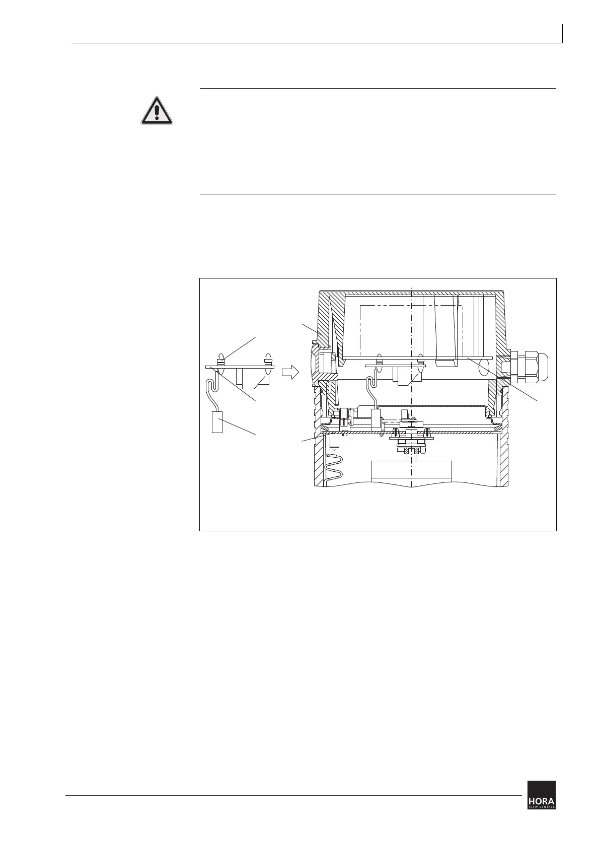
1 Open the linear actuator (201) cover.
4.4 Fit/remove cover on page 14
2 Press the way-switch printed circuit board (106) onto the terminal board (27)
using the (107) three spacers.
3 Place the plug connector bush (115) for the way-switch printed circuit board
(106) on the pin strip (123) on the (110) motherboard. Pay attention to the
grooves in the pin strip and plug connector bush.
27 Spacers
106 Way-switch printed circuit board
107 Terminal board for 24 V or 230 V
115 Plug connector bush
110 Main board
201 Cover for 24 V or 230 V
*
Diagram 11 Installation of the way-switch printed circuit board in the cover