4 Assembly
Linear actuators MC55
Operating Manual Version 3.3 - November 2014 17
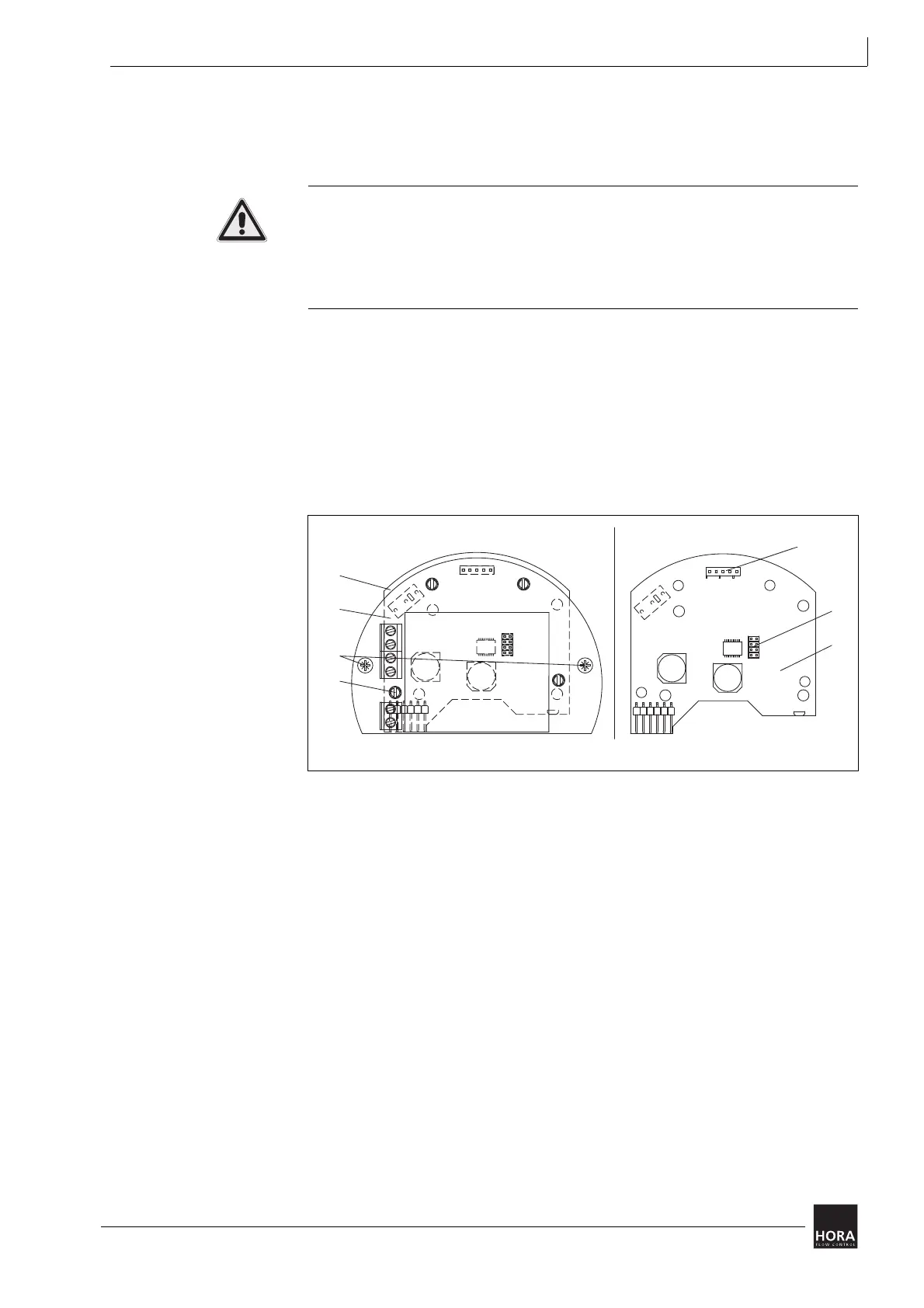
4.5.2 Remove push-fit PCB and transformer MC55/230
To change settings you have to remove the push-fit PCB (107) on the 230 V
model.
Risk of injury from electric shock by live parts!
When the power supply is on there is a danger of electric shock due to live parts.
• Prior to commencing any work, ensure that the actuator is safely disconnected
from the power supply system.
• Secure against unauthorised restarting.
1 Detach the two screws (367)
2 Pull off the push-fit PCB (107) in a straight movement from the spacers (27) and
hold the gear plate by pressing it against the motor.
3 Access to plug-in jumpers (113) JP2 to JP5 is now established.
4 After making changes to the setting carefully put the PCB back on.
Hint: When doing so, make sure that the socket strip fits correctly on the pin strip (124).
5 Tighten both screws (367).
107 push-fit PCB
diagram 8 Remove push-fit CB and transformer
JP2
JP3
JP4
JP5
JP2
JP3
JP4
JP5
113
27
230 V mit Trafo
110
107
110
124
ohne Trafo
367
110
107
367
27
230 V with transformer without transformer
124
113
110