4 Assembly
Linear actuators MC250 • MC253 • MC500 • MC503
20 Version 2.1 - March 2011 Operating Manual
4 Adjust the way-switch.
5.8 Set potential-free way-switch on page 25
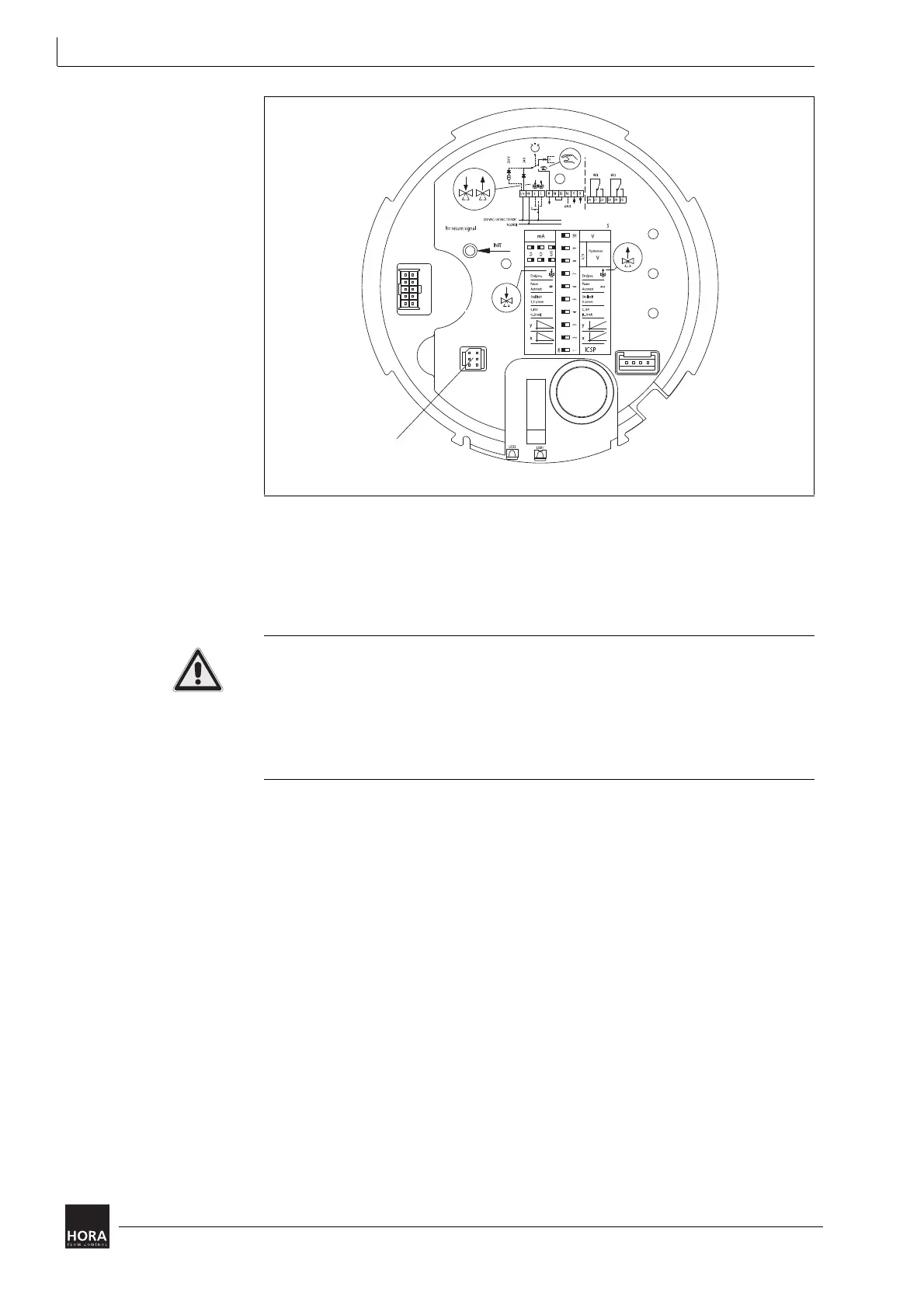
4.6.2 Fit the printed circuit board for mA output signal.
Electric shock due to live components!
If the power supply is switched off, there is danger of electric shock due to live
components.
• Prior to starting work ensure that the actuator is disconnected safely from the
mains power supply.
• Secure against unauthorised switching-on.
1 Open the cover (201) and remove the printed circuit board cover(481).
4.4 Fit/remove cover on page 14
4.5.2 Remove printed circuit board cover on page 18
2 Remove the jumper (JP1) from the motherboard (110).
3 Put the jumper (JP1) onto the plug-in bridge (113) for the printed circuit board for
mA output signal.
4 Plug the printed circuit board for mA output signal (111) together with its pin strip
into the plug-in bridge (113) on the motherboard (110).
5 Lock the spacers (27) into the holes in the motherboard.
123 Pin strip
Diagram 12 Pin strip for way-switch printed circuit board on the motherboard
 Loading...
