5 Commissioning
Linear actuators MC100 • MC103
Operating Manual Version 2.1 - March 2011 23
5.1 Operating parameters and encoding switch settings
Before starting to operate the linear actuator you will have to set the operating
parameters with the help of the encoding switches and jumpers.
5.2 Setting the input signal
Additional information: Input signal (Y) on page 8
5.3 Setting the actuating time
For further information see 2.4.4 Actuating time on page 9
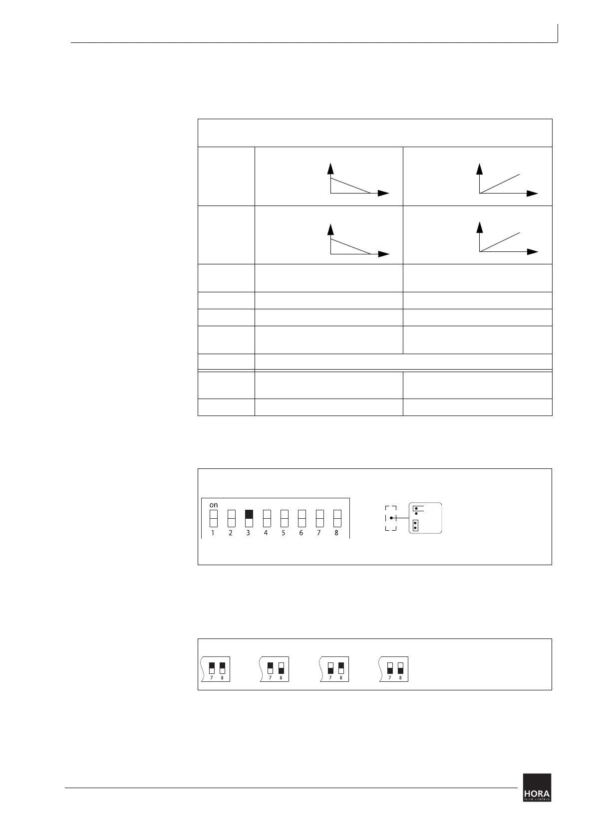
Switch /
jumper
on off
S1 X-
characteristic
line
X-characteristic
line
S2 Y-characteristic
line
Y-characteristic
line
S3 Input signal (Y)
0 … 10 V DC or 0 … 20 mA
Input signal (Y)
2…10VDC or 4…20mA
S4 Hysteresis 0.15 V Hysteresis 0.5 V
S5 Auto test and auto pause on Auto test and auto pause off
S6 Limit position actuator spindle
extended
Limit position actuator spindle
retracted
S7, S8 S7 and S8 are used to set the actuating time (1.9…12 s/mm)
JP1 Characteristic line linear Characteristic line is exponential (1/
50)
JP2 Input signal (Y) in mA Input signal (Y) in V
table 4 Encoding switch and jumper settings
diagram 17 Setting the input signal
0 ... 10 V
0 ... 20 mA
JP2
2 ... 10 V
4 ... 20 mA
mA
V
diagram 18 Set actuating time
4 s/mm 9 s/mm 12 s/mm1.9 s/mm