4 Assembly
Linear actuators MC160 • MC161 • MC163
22 Version 2.1 - March 2011 Operating Manual
5 Set the position switches.
5.8 Setting a potential-free path switch on page 27
4.6.2 Fitting the PCB for the mA output signal
Risk of injury from electric shock by live parts!
When the power supply is on there is a danger of electric shock due to live parts.
• Prior to commencing any work, ensure that the actuator is safely disconnected
from the power supply system.
• Secure against unauthorised restarting.
1 Open the cover (201) of the linear actuator.
4.4 Assembling/disassembling the cover on page 16
224 V: Clip the PCB for the mA output signal to the safety catches inside the cover
(201).
230 V: Push the PCB for the mA output signal onto the three spacers of the (27)
push-fit PCB (107).
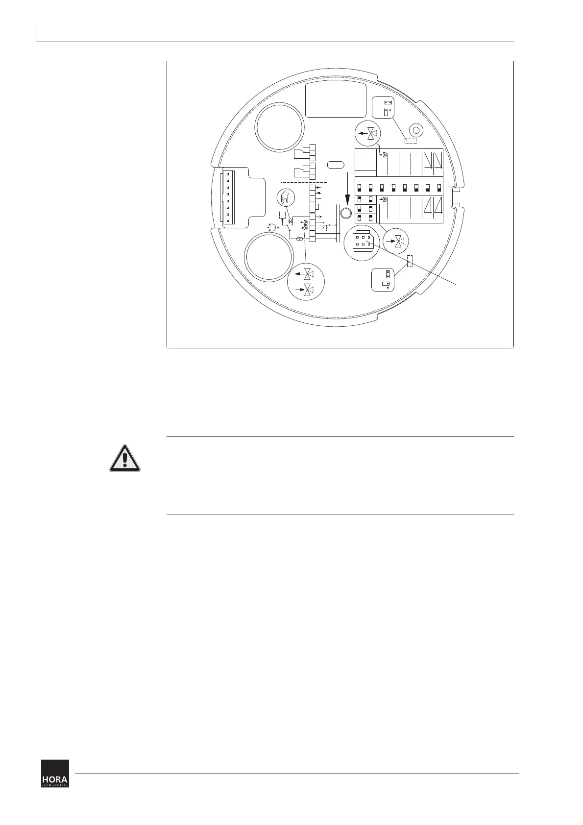
diagram 14 on page 23
123 Socket board
diagram 13 Socket board for position switch PCB on main PCB
123
UB
N1
23R
B1
B2
N2
YX
T
U
N (GND)
24 VDC
24 VAC;
230 VAC;
GND
1000 N
1600 N
JP1
JP2
mA
V
WE2WE1
252423
2221
20
INIT
S
R= return signal
V
Hysterese
ON
0,15
0,05
Endpos.
Autotest
Pause
4 s/mm
Stellzeit
y
Endpos.
Autotest
Pause
6 s/mm
Stellzeit
(4...20 mA)
2...10 V
x
87654321
ein aus
(0...20 mA)
0...10 V
0,3
0,5
y
x