2 Product Specification
Linear actuators MC160 • MC161 • MC163
Operating Manual Version 2.1 - March 2011 7
2.2 Accessories
Hint: Optional operation with mA output signal or path switch possible
2.3 Operating modes
The linear actuator can be operated manually or automatically.
• In manual mode stroke is adjusted via the hand wheel.
• In automatic mode stroke is controlled electrically.
2.3.1 Continuous mode
In continuous mode the system control presets the position of the linear actuator
whilst inside the linear actuator the input signal (Y) of the system control is
continuously compared with the output signal (X) of the linear actuator. In doing
so the output signal depends on the position of the linear actuator (travel).
The linear actuator keeps moving until the input signal and the output signal
match.
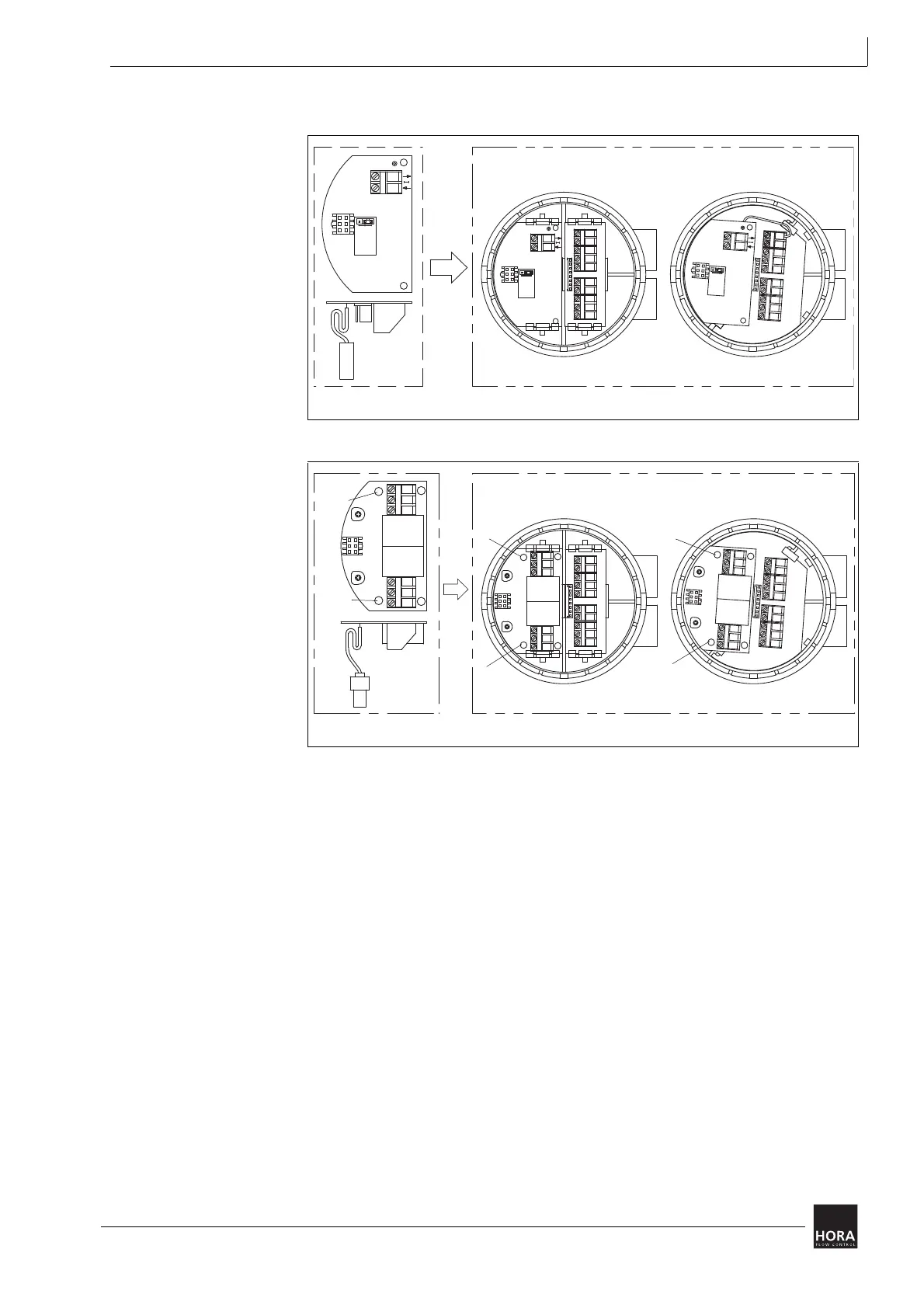
111 PCB for output signal X = 0/4 ... 20 mA
diagram 2 PCB for mA output signal in cover
106 PCB for path switch
diagram 3 Position switch PCB in cover
24 V AC / 24 V DC 230 V AC
X
0..20 mA
4..20 mA
X
N
2
0..20 mA
4..20 mA
X
N
2
0..20 mA
4..20 mA
X
N
2
111
LED2
LED1
LED2
LED1
230 V AC24 V AC / 24 V DC
LED2
LED1
106
LED1
LED2
LED2
LED1
24 V
LED2
106
230 V
LED1